Binary Clock - Easy Arduino Project
The time displayed by the finished clock in the photo
above is 11:44 AM. If you knew that already, then you are at least one
step ahead of this story. The
project started as a salvage operation. What could be done with a
DS3231 real time clock module (RTC) recovered from a no-longer-needed
application, along with an Arduino Uno R3 that had a defective 3.3 volt
rail. ‘Binary Clock’ was the idea that ‘sprang to mind’ as they say.
The first question was how many I/O channels would be needed. The Arduino Uno has 14 digital and 6 analog pins. Assuming
a 24-hour clock, 5 bits would suffice for hours, and 6 bits for
minutes. That requirement consumes 11 digital pins. The real time clock
module can be interfaced using i²c (2 analog pins), leaving a handful
of channels for odds and ends, such as serial interfacing and
time-setting.

There were more blue LED’s than other colors in the
5 mm LED storage drawer, so blue was the first color to be tried. It
was a poor choice. Blue is perfect for ambulances and police cars but
not for binary clocks. Part of the problem was the eye-level location
that had been planned for deploying the clock. Viewing the LED array at
an angle from above was not bad, but straight-on viewing was painful.
At first, the common (positive) side of the array
was connected directly to the 5-volt source. I increased the eleven
series resistor values to 5600 ohms each. This configuration equated to
less than 1 mA current per LED at 5 volts. Surely that would be dim
enough. It wasn’t. There was nothing for it but to replace the blue
LED’s with red colored ones, red being the lower energy end of the
visible light spectrum. This change made a significant improvement, but
the array was still too bright at eye level.
After testing the color change with the same-valued
resistors as were used with the blue LED’s I tried out other larger
resistor values on a breadboard. At some point my wife asked if it
wouldn’t be simpler to insert an additional resistor on the common
side. Sometimes the obvious isn’t... In any case her suggestion led to
the dimmer control that is shown in the diagram above. Each fixed
series resistor is 5.6 K and the dimmer trimmer is 50 K.
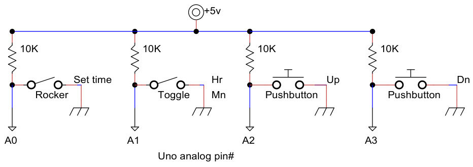
Arduino analog pins can be read in digital mode as
HIGH or LOW valued, the same as digital pins. In this project
everything is low-enabled. In other words, LOW corresponds to LED
illuminated, or switch ON, or pushbutton depressed. Analog pins A4 and
A5 are used for interfacing the DS3231 real time clock, corresponding
to SDA and SCL respectively. For neatness sake the other four analog
pins were assigned the functions depicted in the diagram above. The
rocker switch was mounted on the back of the enclosure and is therefore
not visible in the photo at the top of the page. When the rocker switch
is off, the pushbuttons and toggle switch have no effect. The same is
true of setting time from the Arduino IDE. In order to set time by any
means, the rocker switch must be ON. It is a good idea to switch it off
after setting time, for the obvious reason.
The Arduino sketch may be viewed or downloaded here
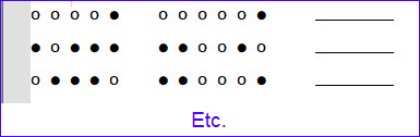
(right-click, SaveAs). It takes a little practice to read times
fluently, especially in a dark room where only illuminated LED’s can be
seen, and you have to guess where the gaps are! To help with acquiring
proficiency in this arcane skill I have included a training feature in
the sketch. At the bottom of the setup() function there is a
commented-out statement, which when enabled prints a set of 50 example
binary clock times to the serial monitor. Times are random so each run
produces a fresh set of examples.
This project and sketch rely on the DS3231 RTC for
time of day, and also require the Arduino library RTClib.h from
Adafruit for interacting with the RTC. This library should be installed using the Arduino Library Manager. Some microcontroller prototyping kits include integral clocks.
If a different hardware clock is used for the project, then a different
library may be required, which in turn may expose different methods of
reading or setting the time. In general the concepts will be the same
and it should not be difficult to adapt the sketch for another platform
if desired.
Project descriptions
on this page are intended for entertainment only.
The author makes no claim as to the accuracy or completeness of the
information presented. In no event will the author be liable for any
damages, lost effort, inability to carry out a similar project, or
to reproduce a claimed result, or anything else relating to a decision
to
use the information on this page.
