DC to DC Power Supplies — Buck
and Boost Converters
As is true of most of my projects this one was
motivated by a wish to understand something. I had used DC-to-DC power
supplies in a few small electronic projects without having a clear idea
of how they work. I began by reading articles about Buck converters.
Most of these articles included circuit descriptions, and some
suggested ‘Do it yourself’ (DIY) type exercises.
After reading probably
a dozen different articles (web pages) I felt that I understood the
basic features of these circuits and wanted to test my understanding by
constructing a working circuit. The circuits that I made were
bare-bones—demonstration-only. They were based on canonic designs that
I had seen reproduced in multiple sources. These simple circuits do not
include feedback to adjust for a variable load, or any other
refinements. They simply demonstrate how one DC voltage can be
converted to another using a switching circuit with adjustable on/off
times.
There is nothing original in my demonstration
project. It is
simply an adaptation of what I had read. The end-results are shown in a
5-minute video that emphasizes conceptual principles, but
omits details such as circuit component values.
Video: Buck Converter
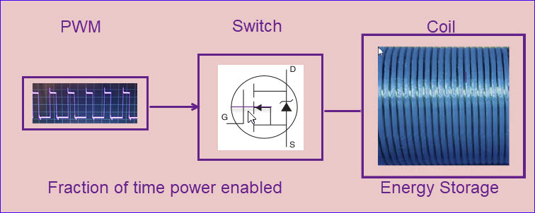
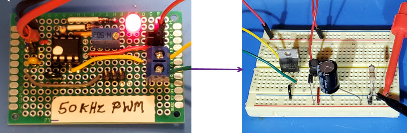
PWM stands for ‘Pulse Width Modulation’. For the PWM
circuit I used the ubiquitous 8-pin DIP 555 integrated circuit as
diagramed on page 172 of the TTL
cookbook. The circuit I constructed was almost identical to the one
described at this instructional page. The
555 frequency was a little under 50 KHz, C = 470 pF, R1 + R2 = 50K
(multi-turn trimmer potentiometer). The output
of the 555 PWM gated an IRFZ44N
transistor (MOSFET). The inductor value was 100 μH. Different
electrolytic capacitor values (180 μF to 1000 μF)
and test
loads were tried for experimentation. Pretty much everything worked in
the expected way.
In summary, DC-to-DC
converters are a type of switching power-supply. Input power is
switched on and off at a high rate of speed. The fraction of time that
the switch is on during each on-off cycle (the pulse width) determines
the amount of energy that can be made available for use by the load.
Well-engineered Buck and Boost converters use feedback circuits to
maintain a constant output voltage under varying load. This is more
efficient that the use of voltage regulator ICs, which necessarily lose
significant energy in the form of heat.
Project descriptions
on this page are intended for entertainment only.
The author makes no claim as to the accuracy or completeness of the
information presented. In no event will the author be liable for any
damages, lost effort, inability to carry out a similar project, or
to reproduce a claimed result, or anything else relating to a decision
to
use the information on this page.