GPS
Disciplined Frequency Counter
A clever idea:
I have written about several QRP (low power) ham radio transceiver
kits. One of these, the single band QCX
from QRP
Labs boasts a feature not seen in similar rigs.
It is the next to last item noted in the kit’s Features
list, “GPS interface for reference frequency calibration and
time-keeping (for WSPR beacon).”
By way of background, the QCX relies on
the popular Silicon Labs Si5351A clock generator/VCXO for
frequency generation. VFO accuracy depends
on the precision of the
clock generator’s 27 MHz crystal. The firmware part of frequency
generation and everything
else in the QCX transceiver utilizes an Atmel ATmega328P
microcontroller running at 20 MHz.
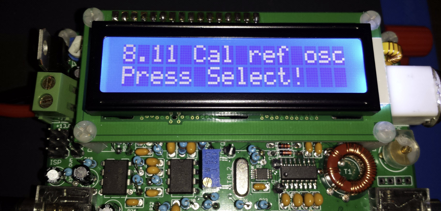
Now to the magic. If the
pulse-per-second signal from a GPS is connected to the QCX transceiver,
a simple button press (at menu option 8.11) will cause the unit to
count cycles at one fourth the crystal frequency for precisely four
seconds, thus obtaining a value for the true frequency of the crystal,
or equivalently a calibration value for the QCX frequency generator.
Puzzle:
If you think about the arithmetic, one fourth of 27 MHz is 6.75
MHz—that is 6.75 million counts per second. The QCX MPU clock speed is
20
MHz, so the counting rate is one count per just-under-three MPU clock
cycles (20 ÷ 6.75), which seems impossibly fast, but is manifestly not
so. My ATmega328P programming experience was limited to the Arduino IDE
context, so at this stage of puzzlement I experimented with a 16 MHz
Arduino Uno, using an ordinary interrupt service routine (ISR) to count
clock cycles, starting
at low frequencies and gradually increasing the rate. The ISR contained
only one command ‘count++’
(increment the count by 1).
The maximum rate that could be measured in this test was approximately
130 KHz, orders of magnitude below the counting rate of the QCX
calibration procedure.
Uncle! The
exclamation “Uncle!”
is an Americanism meaning “I give up.”
Giving up is not my usual style. I have had another puzzle in my head
for more than two years already, without saying Uncle! Be that as it
may, after a few days I Emailed an enquiry to QRP Labs asking how they
do this magical thing. ‘They’ is Hans G0UPL, who very kindly replied to
my Email, explaining how he does it.
In the QCX, during frequency calibration I set the Si5351A Clk2 output
to be 1/4 the reference frequency. There is no synthesis at all going
on, the Clk2 output is merely defined to be fed directly from the 27MHz
reference clock, and using a division by 4, to reach about 6.75MHz.
Since AVR ATmega328 devices can use their 16-bit Timer1 to count at up
to 40% of the system clock (20MHz), which would be 8MHz maximum, the
supplied 6.75MHz is within limits to properly clock Timer1.
Then the 1pps signal generates an interrupt (pin change interrupt),
which is used to latch the state of the Timer1 counter. The difference
between two consecutive readings is the frequency. The Timer1 is
effectively acting just as a simple frequency counter where the 1
second timing gate (latch) is supplied by the 1pps from the GPS.
The error is +/- 1Hz (the least significant bit uncertainty always
present in frequency counters). Since I have set the Si5351A Clk2 to
1/4 the reference frequency, the error in the calculated 27MHz
reference is then 4x this, i.e. 4Hz. I wanted to calibrate to an
accuracy of 1Hz so therefore I measure 4 seconds, instead of 1 second.
This gives me the 1Hz accuracy at 27MHz.
Hardware
versus Software:
That contest is over—software won! Upon reading the explanation quoted
above, I set about to study ATmega328P timers and registers, and
carried out a few exercises, but not the one that Hans so lucidly
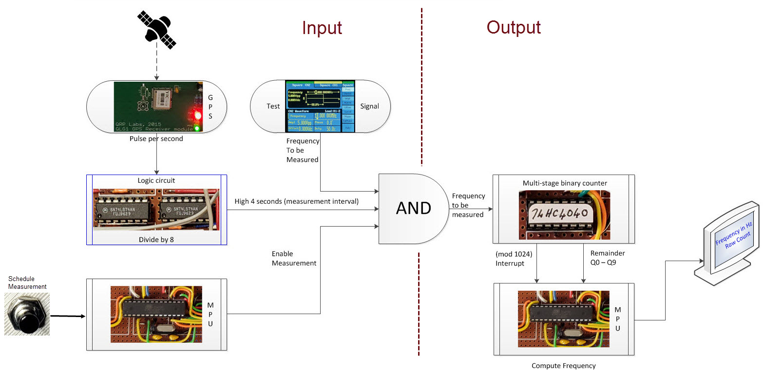
described. As brain fatigue set in, I thought of an alternative way to
measure
frequencies up to a few tens of MHz by doing part of the work in
hardware. The same GPS gating concept would be applied, but the
frequency to be measured would first be divided to a lower frequency,
so that an ordinary Arduino ISR could count blocks of cycles, and add
the remaining partial block in a final calculation. I had most of the
logic components on hand to try this out, but needed to order one type
that I did not have, a 74HC4040 12-stage binary counter. It
would have been possible to use a pile of flip-flops, but a
single-chip counter would be much simpler.
In truth I wasn’t dead sure the ~4040
would work, as I had never used one. From the datasheet description it
seemed that it should. Anyway, if it did not, I would still learn
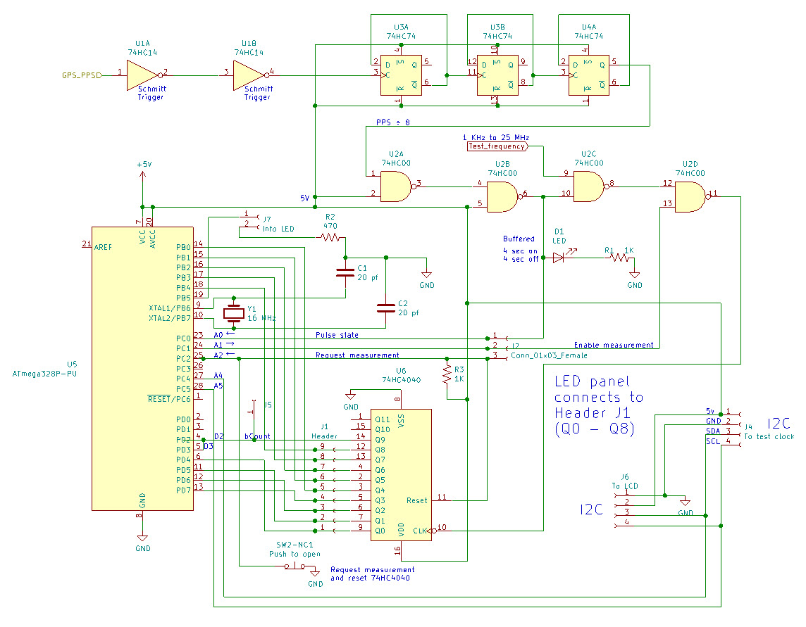
something. While waiting for delivery of the
chip order, which included replenishment of a few other components, I
started to wire things up, working from both ends at once. I wired the
PPS divide-by-8 circuit and tested the 4-seconds on, 4-seconds off with
an
LED. At the other end I wired up an array of LEDs. After considering
several options I decided to divide the measurement frequency by 210,
which is almost the same as converting MHz to KHz. From previous
experience I knew that counting to a few tens of KHz would pose no
problem.
By the time chips were delivered (less
than a week) I had wired a 16-pin DIP socket for the 74HC4040, and had
partly tested the circuit. The GPS was in a different room,
where it could be pointed
toward a window for optimal reception. So, as a temporary measure for
bench testing, the function generator was set
to emulate a GPS,
outputting a 1 Hz square wave, or a pulse-per-approximate
second, close enough to tell if the rest of the circuit was working or
not. It was not. Well, the whole number part of the
calculation (the number of 1024 bins) was working, but the remainder
was not right. The value the program had was not the same as the binary
number displayed by the row of LED’s connected to the counter chip.
Troubleshooting:
There were two problems. One was software—I
had intended to read the interrupt pin, after counting was complete.
This did not work, so I tied that bit to another pin as well. In other
words, the same 74HC4040 pin connected to two digital input pins on the
ATmega328P, one attached to an interrupt on the falling edge, and the
other available to read on demand.
The second problem was a tiny speck of solder between two pins. I
discovered this by testing voltages and finding that two of the sensing
pins on the MPU were at half voltage, which should have been
impossible. Upon correcting this second problem the (mod 1024)
number that was displayed on the LCD debug data line corresponded
to the binary value displayed by the LED’s. Moreover the displayed
frequency result was close to the presumed test frequency, but
varied a few Hertz from trial to trial.
 GPS:
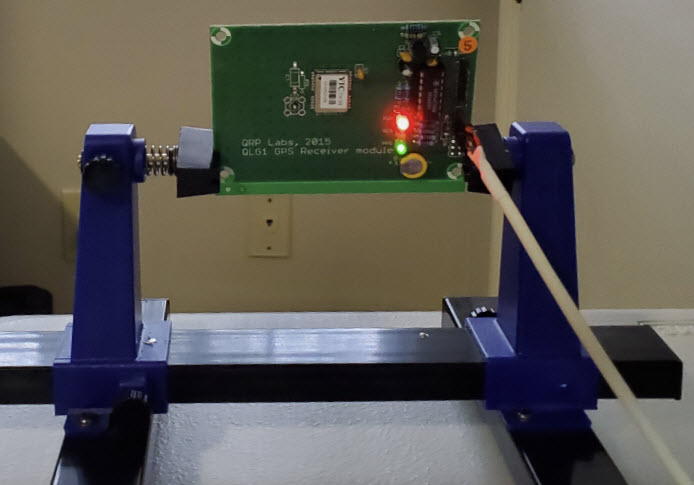
It was time to connect up the GPS,
so I moved the rather shaky prototype setup from the bench to where the
GPS was busy counting seconds to no useful purpose. And now a new
problem presented. Anytime the GPS was switched into the circuit it
lost synch and stopped issuing PPS. I tried many things, most too
embarrassing to mention, but in the end hit upon the cause. The GPS was
connected to a different power supply than had been used in bench
testing the logic circuit. It was an old home-brew power-supply of
questionable merit. On connecting the entire setup (GPS and logic
circuit) to the bench supply, the GPS immediately behaved normally and
reliably—in other words, it synched quickly every time it was switched
on.
GPS:
It was time to connect up the GPS,
so I moved the rather shaky prototype setup from the bench to where the
GPS was busy counting seconds to no useful purpose. And now a new
problem presented. Anytime the GPS was switched into the circuit it
lost synch and stopped issuing PPS. I tried many things, most too
embarrassing to mention, but in the end hit upon the cause. The GPS was
connected to a different power supply than had been used in bench
testing the logic circuit. It was an old home-brew power-supply of
questionable merit. On connecting the entire setup (GPS and logic
circuit) to the bench supply, the GPS immediately behaved normally and
reliably—in other words, it synched quickly every time it was switched
on.
 And now something
amazing happened.
Successive
trials at the same test frequency produced the same result, within 1
Hz. The reason is that the one-second GPS pulse is more precise than
the simulated PPS from the function generator. [Specifically, the PPS
signal from the YIC5 series chip in the QLG1 has a
claimed accuracy of ± 11 ns.] An
observation that is logically expected can still be surprising! I
tested the same frequency
repeatedly, as if
expecting an
aberrant result
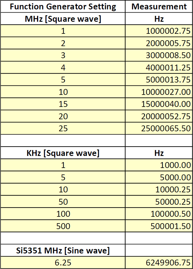
on the next measurement. Eventually I stopped perseverating, and
instead ran a systematic test across a range of frequencies. For this
exercise I used the function generator as a source of test frequencies,
from 1 KHz to its maximum 25 MHz limit. Each frequency was tested a
couple of times, with consistent readings.
And now something
amazing happened.
Successive
trials at the same test frequency produced the same result, within 1
Hz. The reason is that the one-second GPS pulse is more precise than
the simulated PPS from the function generator. [Specifically, the PPS
signal from the YIC5 series chip in the QLG1 has a
claimed accuracy of ± 11 ns.] An
observation that is logically expected can still be surprising! I
tested the same frequency
repeatedly, as if
expecting an
aberrant result
on the next measurement. Eventually I stopped perseverating, and
instead ran a systematic test across a range of frequencies. For this
exercise I used the function generator as a source of test frequencies,
from 1 KHz to its maximum 25 MHz limit. Each frequency was tested a
couple of times, with consistent readings.
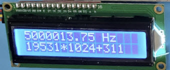
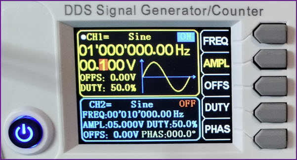
Arithmetic:
An example will illustrate the arithmetic. While the Siglent function
generator’s maximum frequency is 25 MHz, the Si5351 clock generator can
be programmed to higher frequencies. The Adafruit breakout board
for the Si5351 (no suffix) is marked 8 KHz to 160 MHz. I decided to try
a measurement at 40 MHz. At that frequency the duration of 1 full cycle
is 1 ÷ 40,000,000 = .000000025 seconds, while the YIC5 series GPS
pulse-per-second (published) accuracy is .000000011 seconds. Both those
small decimal numbers have 7 zeros (hard on the eyes). The illustration
below shows the result of a measurement of the Si5351-generated 40 MHz
signal. The clock generator was plugged in cold—no warm-up
time.
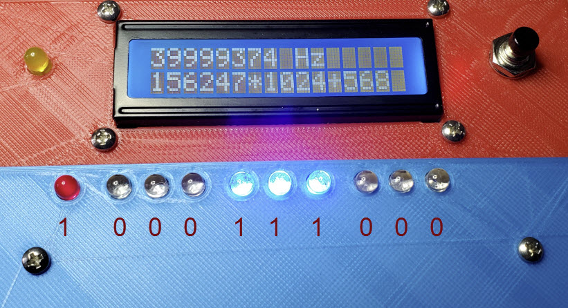
The displayed frequency count is 39,999,374 Hz or 626 Hz below the
programmed frequency. This difference reflects the accuracy (or error)
of the Si5351’s
25 MHz crystal clock.
The second line of the display shows the raw count data from which this
frequency was computed. 156,247 blocks of 1,024 + 568 cycles were
counted during the 4 second sampling interval. That is 159,996,928 +
568 = 159,997,496 cycles over 4 seconds or 159,997,496
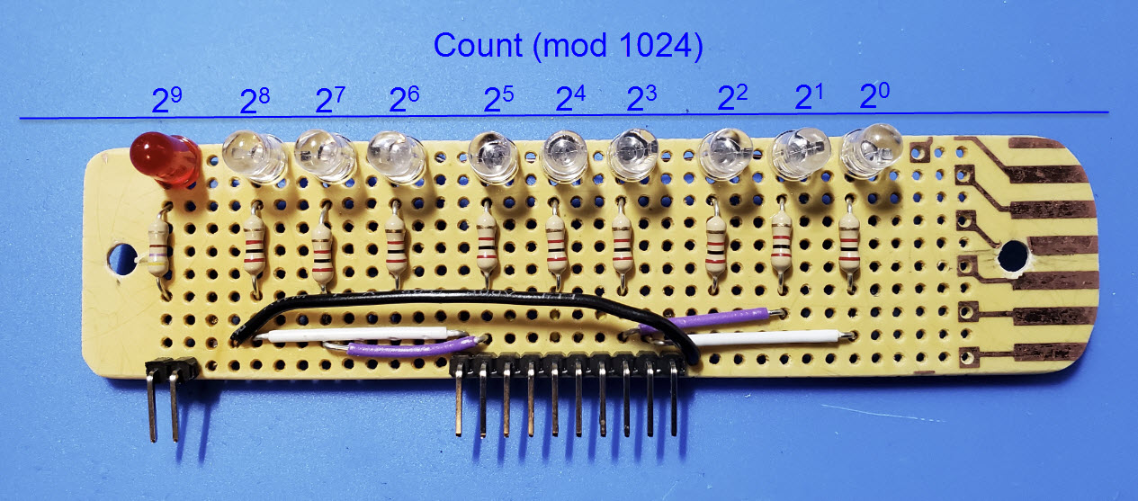
÷ 4 = 39,999,374 cycles per second (Hz). The LED panel (used during
construction for debugging) displays the remainder value in binary.
Each is connected to an output of the 74HC4040 binary counter. The most
significant bit is the red LED. (Binary 1000111000 is decimal 568.)
What fun: In the past I have constructed a few crystal
oscillators, and have played with the Analog Devices DDS as well as the
Silicon Labs PLL clock generator. There is something uniquely appealing
about precise measurement. I realize that my ‘precise’ is not
the same as laboratory precision. However, the precision of the GPS
time duration signal exceeds that of most other measurement references
accessible to hobbyists.
Unnecessary complexity: As much as I like the binary
display—it reminds me of those mid-1970’s micro- and
mini-computer panels—that display, and more importantly the
concept on which
it was based, is unnecessary. When I described this project to Hans
G0UPL, he told me in a gentle way of a similar project he had done a
half-dozen years previously. As with the QCX calibration, Hans’ earlier
frequency counter project
exploited software to perform nearly all logic functions, including
dividing and gating the PPS, prescaling the frequency count, and
reading the modulus. Of all the efficiencies (and there are
several) this one struck me as exceptionally creative.
..when I want to read the value from the counter, all I have to do is
cause the processor to toggle the PB0 pin which is connected to the
74HC4040's input clock, and count how many pulses I have to send, in
order to change the state of the most significant bit! Then I can
calculate easily, what the counter value was before I started the
pulses!
Sooner or later I will need to learn AVR
programming beyond the shelter of the Arduino IDE. With
proper use of Hans’ suggestions it
would be possible to do this project
with just one or two chips, no flip-flops or NAND gates.
But that will be another story.
Demo video: GPS_Frequency_Counter.mp4
Later (Two improvements): Not long after posting the above
I implemented Hans’ suggestion to toggle the PB0 pin and count pulses
up to 0, thereby freeing up microcontroller input pins, as
well as simplifying the logic. I left the binary LED display and
associated circuitry in place, though no longer needed. Flashing lights
are always good.
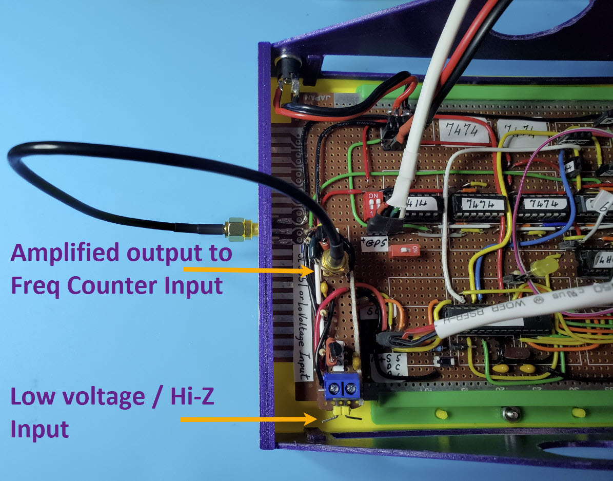
The second ‘improvement’ extends the
functionality of the counter to enable measurement of low voltage/high
impedance sources, such as VFOs or receiver IF circuits, etc. This
enhancement was made possible by a happy accident. Four
States QRP Group announced a re-release of their Freq
Mite kit designed by Dave Benson K1SWL. Upon examining the schematic for this kit, I
realized that its input circuit would work for my purpose as well. I
ordered the kit from 4SQRP ($22 including shipping) and immediately
began to construct the
input circuit on a breadboard using parts on hand (substituting
2N3904 for the 2N4401 transistors specified).
After testing, I transferred the circuit
to a small cut piece of generic PCB. The GPS Frequency Counter
mainboard included a socket for an Si5351, which was used in testing
the original circuit during construction. Two header pins on the bottom
of the add-on PCB mate with the Si5351 socket for the 5 volts needed to
power the transistors. (A single unconnected pin plugs into the other
end of the test socket to facilitate alignment.)
Last Hurrah:
Later I redid this entire project as an exercise in using surface
mount components (resistors, capacitors, IC’s, etc.) in place of
through-hole and DIP devices. For details on this redesign, including
schematic and MPU sketch, see the full description here.
The following video demonstrates
counting a couple of weak signals. In the second part, a 100 millivolt
sine wave is boosted
sufficiently to drive a NAND gate. The NAND gate’s output pulses the
main
counter. The video also shows the other change (counting the
remainder bits up to 0), although you have to look quickly to see it.
Demo video (supplement): LoVoltage_Input.mp4
Project descriptions
on this page are intended for entertainment only.
The author makes no claim as to the accuracy or completeness of the
information presented. In no event will the author be liable for any
damages, lost effort, inability to carry out a similar project, or
to reproduce a claimed result, or anything else relating to a decision
to
use the information on this page.