I
made no effort to optimize the display modifications. It is possible
that the compiler warning might be avoided by removing redundancies,
replacing strings with small character arrays, and making other
efficiencies. On the other hand no actual stability problems were
observed in the course of exercising the display.
Demo:
OLED-demo.mp4
Receiver
Incremental Tuning:
The
LCD and OLED displays described in preceding paragraphs
show frequency and tuning step, but
not
Receiver Incremental Tuning (RIT). Shortly after the
Hilltopper LCD modification was posted, another ham (NK8O)
created an
enhancement to include
RIT status along with frequency and keyer speed information
in the display
(posted
to HilltopperKit@4sqrp.groups.io).
This
improvement sparked
my awareness of RIT, and prompted me to read the relevant paragraph
in the instruction manual. A crazy thought sprang to mind: Would it be
possible to display both main frequency and RIT information from the
Hilltopper using Ham Radio Deluxe (HRD)?
I imagined inserting a small number of CAT commands
into the Hilltopper’s
microcontroller code, just enough to communicate minimally with HRD. I
did not know which or how many commands
would be needed for a working interface. To probe the
possibilities I set up a test situation using the com0com
utility
to
establish
two virtual COM ports, and to configure them as a
null-modem pair. Next I attached
the
terminal
emulator
program Termite to
one of the ports. Finally, I created a ‘connect’
target entry in HRD, associating the other
COM port of the pair with the Kenwood
TS-440S rig type.
Using this test setup, I attempted to connect HRD in effect to Termite.
In this way it became possible to observe CAT commands from HRD
in Termite’s ‘receive’
area. While attempting to establish a connection, HRD requested
VFO-A and
VFO-B
frequencies (FA and FB commands), general information (IF command) and
the status of frequency and tuning locks (LK command). To be sure those
commands were all that HRD would require to connect and remain
connected, I typed
artificial replies to each command into a text document, then copied
and
pasted them as fast as I could into the terminal emulator’s ‘send’
box. Fortunately HRD is patient—it
does not report failure to connect until multiple command repetitions
have gone
unanswered.
Through trial and error I found that it
was acceptable to join replies end-to-end. In other
words, sending superfluous information or data that HRD had not
specifically requested did not break the connection. Repeating Paste and Enter every few
seconds kept HRD connected indefinitely. In place of probing HRD
in this way
(like a
black box), it might have been more efficient to study the manual. In
any event I concluded that
programming the Hilltopper to supply answers to these commands
would suffice to keep the connection alive.
This conclusion led to a 2-phase coding
plan. In the first phase, frequency information would be transmitted
from the Hilltopper to HRD for display as VFO-A. Then the reverse:
changes to HRD’s VFO-A should produce corresponding frequency changes
in the Hilltopper (bounded by the band edges, of course). Once primary
frequency information was flowing in both directions, the second
phase of coding would address RIT. Although I had no clear idea how to
do this, it seemed that the
Hilltopper’s
RIT function
should somehow link with HRD’s
VFO-B component.
The process of coding and testing was
not without glitches. For example, sometimes the frequency
display would flutter once between the last value and the currently
tuned
value. This was corrected by updating the Hilltopper frequency and LCD
synchronously whenever frequency was adjusted in HRD. Another example
is VFO-B change direction in relation to RIT delta—the direction was
inverted on the first try. (That fix was trivial.) I feel sure that
communication could be streamlined, and possibly HRD’s display
responsiveness could be improved. However, once the interface was
working I felt little urge to improve it.
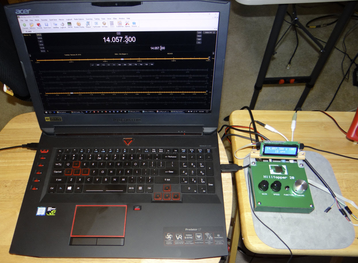
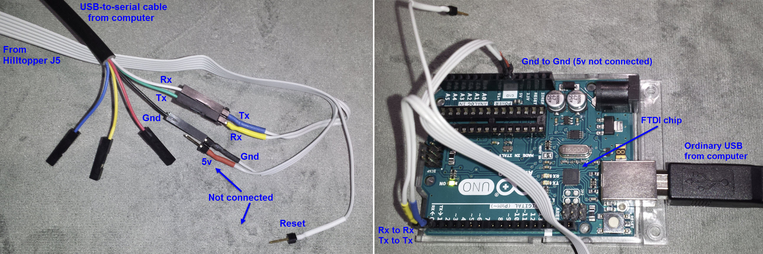
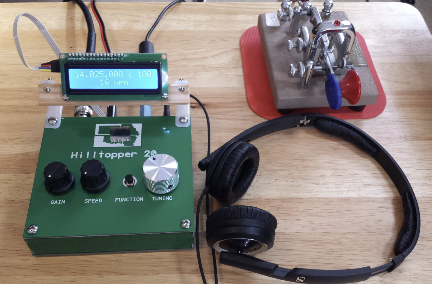
Electrical interface: The above photos illustrate two
options for connecting the Hilltopper with a computer running Ham Radio
Deluxe. They are conceptually the same, each implementing a USB
(computer port) to serial (Hilltopper) connection. In the left photo
the USB-to-serial cable has an FTDI chip
embedded in its USB-A connector (the computer end). I also tried a
cable that had an embedded PL2303 chipset. That one did not work for either
the
present project or another project
that also needed a bidirectional computer-to-microcontroller
connection.
Note that although very old PCs may have one or more hardware serial
ports (RS-232), these typically use higher voltages and are not suitable
for microcontroller interfacing, or would require converting levels.
Demo: Hilltopper-HRD-CAT.mp4
Project descriptions on this page are intended for entertainment only.
The author makes no claim as to the accuracy or completeness of the
information presented. In no event will the author be liable for any
damages, lost effort, inability to carry out a similar project, or to
reproduce a claimed result, or anything else relating to a decision to
use the information on this page.

 >
>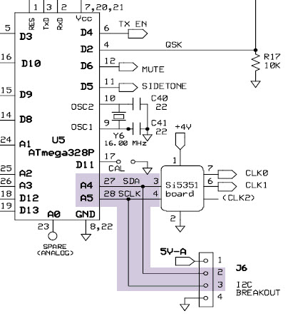
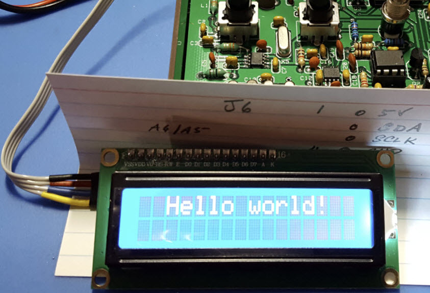 A quick glance at
the schematic detail above reveals that J6 breaks out the i2c
bus.
The main use of i2c is for communicating with the VFO (Si5351 DDS), but
of course a different (though related) application springs to mind. To
that
end I soldered a four-pin header into J6 and made a connecting cable to
use with a 2-line LCD. The first test was to ascertain whether writing
to the LCD would interfere with anything else. It did not!
A quick glance at
the schematic detail above reveals that J6 breaks out the i2c
bus.
The main use of i2c is for communicating with the VFO (Si5351 DDS), but
of course a different (though related) application springs to mind. To
that
end I soldered a four-pin header into J6 and made a connecting cable to
use with a 2-line LCD. The first test was to ascertain whether writing
to the LCD would interfere with anything else. It did not!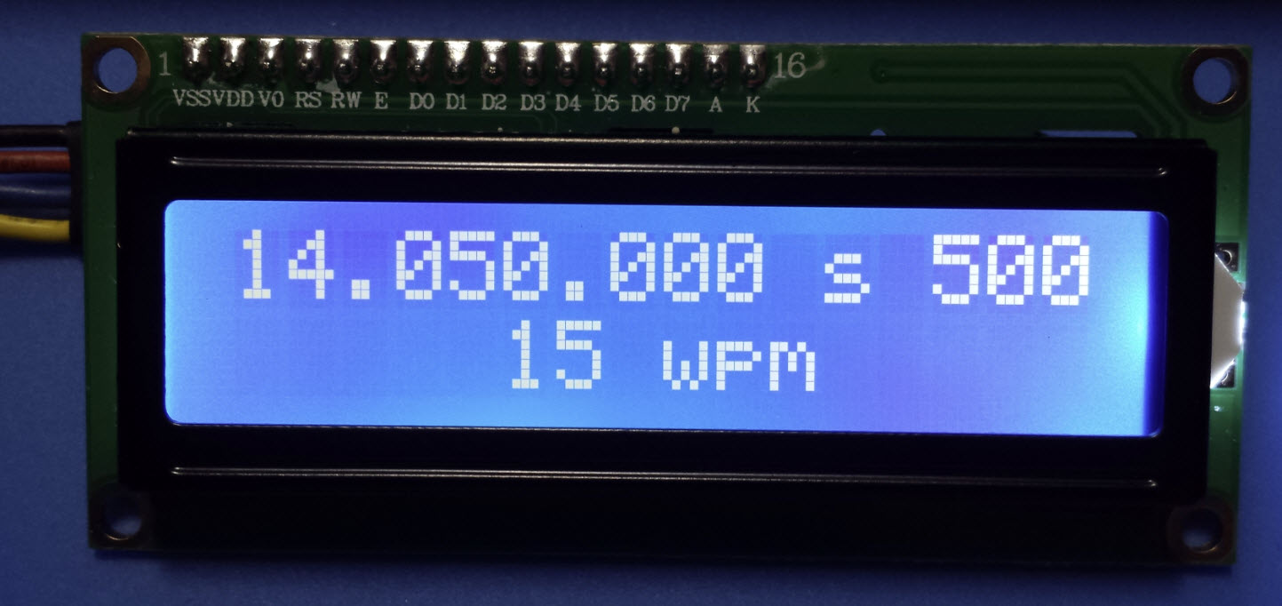
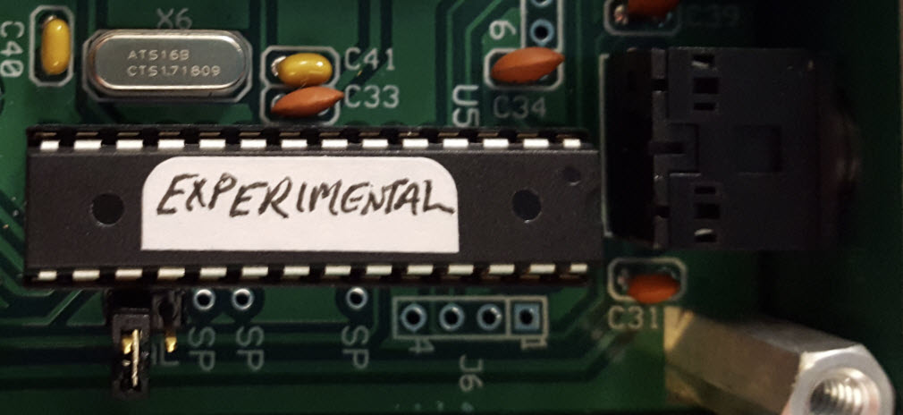
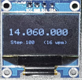 Third thought:
Sooner
or later I will let this thing go. The display device pictured on the
left is a 0.96 inch OLED. It is tiny and possibly thin enough to fit in
the Hilltopper enclosure. However, I will not be cutting holes in my
Hilltopper panel—holes
cannot be uncut and such ambitious undertakings always go wrong for me!
Third thought:
Sooner
or later I will let this thing go. The display device pictured on the
left is a 0.96 inch OLED. It is tiny and possibly thin enough to fit in
the Hilltopper enclosure. However, I will not be cutting holes in my
Hilltopper panel—holes
cannot be uncut and such ambitious undertakings always go wrong for me!