Automatic Control of RCA TV
Antenna Rotator for Satellite Azimuth Tracking

 Many ham radio satellites operate at frequencies similar to those that
were used by VHF and UHF TV stations in the years before cable or
satellite TV. Therefore, antennas that are suitable for ham radio
satellites on the 2 meter and 70 centimeter bands are of similar size
and weight as the old roof-mounted outdoor TV antennas, the kind that
were popular in rural areas, some distance from the TV tower.
Many ham radio satellites operate at frequencies similar to those that
were used by VHF and UHF TV stations in the years before cable or
satellite TV. Therefore, antennas that are suitable for ham radio
satellites on the 2 meter and 70 centimeter bands are of similar size
and weight as the old roof-mounted outdoor TV antennas, the kind that
were popular in rural areas, some distance from the TV tower.
My satellite antenna
(photo left) is designed to be hand held. Notice the bumbershoot handle
at the
right hand end of the boom. The antenna is actually two antennas on one
boom.
The four larger elements are for the 2 meter band, while the
orthogonally-mounted multi-element Yagi is designed for the 70
centimeter band.
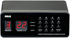
Since the Arrow antenna is similar in size and weight to an outdoor TV
antenna, it can be rotated using a TV antenna rotator such as the RCA model VH226E. Of course this
rotator only tracks the satellite’s azimuth, not its elevation. Ideally
the antenna would point directly toward the satellite, not below or
above it. However, rotators that control both azimuth and elevation are
specialty products—not low-cost consumer items.
As the photo shows, my antenna is mounted at a fixed
elevation angle of approximately 30 degrees. I was aiming for 20
degrees but left the heat gun on too long! In any case, it is a typical
setup for a modest amateur radio satellite station. A great many other
ham operators use exactly the same antenna and TV antenna rotator as I
am using. Of course, the rotator was never meant to be used in
this way, so it does not have a computer interface. The intended
application goes something like this: You sit on the couch in front of
the TV with remote control in hand, pushing buttons until the snow
disappears, or the picture stops scrolling. In this once
easy-to-imagine
activity lies the key to a solution for satellite azimuth tracking.
The remote control: How does that thing
work anyway? The signal that passes from the handheld remote to the RCA
controller box is modulated infrared (IR) light. The remote emits IR
signals that are received by a sensor in the controller box. As it
happens, IR sensors and emitters are a common item of interest to
electronics hobbyists. They are used with remote control vehicles and
robots and so forth. For this same reason, application examples are
also
commonplace. When the idea occurred to me that it might be possible to
receive and decode signals emitted by the RCA TV rotator
remote, I had no inkling of how easy
this would turn out to be. In fact that part of the problem was already
fully solved by an example sketch that is included with the Arduino
IRremote.h library. I connected a sensor—yes there was one in the
drawer. (Finding long forgotten small things is one of my wife’s many
gifts.)
In no time at all I had a listing of the codes that are produced by pressing
either memory buttons or arrow buttons, the latter for producing
arbitrary degrees of rotation.

IR sender: We are already near the end of
the hardware part of this story. To test whether the codes that were
intercepted from the remote could be used to activate the RCA tabletop
controller, I loaded an IR emitter example sketch to an Arduino Uno
(not shown) and first sent the codes to the test IR sensor rig. There
they were received and interpreted the same as codes from the remote
itself. After that I sent them to the RCA controller and of course they
worked the same there as well.
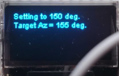
At this point I began to think about a full-fledged
azimuth interface. For this project I selected the Heltec WiFi Kit
32(V3) that is shown in the photo above. There were two reasons for
choosing the Heltec. First,
one was sitting on my desk waiting to be used for something, and second
I thought the integrated OLED display might be useful for providing
feedback regarding azimuth adjustments as they were being made. There
was a third reason, but I’ll defer that one for now.
Wiring and setup: As
the above photo shows, very little wiring is needed to complete the
interface. The input format is serial,
either 3 volt TTL (orange to green to GPIO 47 in the photo) or RS-232
(move the green jumper to the 3 volt TTL output of the RS-232 to TTL
adapter). The IR emitter signal is also 3 volts (GPIO 4 white to
yellow in the photo). The rest is just power supply wiring.
The input source that supplies serial azimuth data
by way of the 3.5 mm mono jack is a custom microcontroller-based
satellite tracking device. My Sats Helper outputs the same parameters as popular satellite tracking computer
applications do, including Doppler corrected transmit and receive
frequencies, azimuth, elevation, and range etc. However, a full
description of the source
data component, whether computer-based or standalone is beyond the
scope of this interface project summary. It should only be necessary to
understand the format of the azimuth data that are transmitted to the
IR interface via a serial wire. The data format is configurable in the
sketch, but by default is a subset of the EASYCOMM-1 interface format. Only one command
element is needed AZxxx, where
xxx stands for a 1 to 3 digit
target azimuth. The command is terminated by CR (0x0D).
 A ham radio satellite friend Roger (N1NN) suggested preloading the RCA
rotator controller’s letter-labeled memories A, B, C, ..., J, U, L with
the values 0°, 30°, 60°, ... 270°, 300°, 330°. This facilitates
rotating to an initial azimuth value that is possibly far from the
antenna’s starting
position with just one button press. As presently implemented, the
IR interface depends on this convention, as it first commands the
controller to rotate to the 30° multiple that is
closest to the target azimuth, and then emulates a timed arrow
button press for the final few degrees (less than 15°) of adjustment.
A ham radio satellite friend Roger (N1NN) suggested preloading the RCA
rotator controller’s letter-labeled memories A, B, C, ..., J, U, L with
the values 0°, 30°, 60°, ... 270°, 300°, 330°. This facilitates
rotating to an initial azimuth value that is possibly far from the
antenna’s starting
position with just one button press. As presently implemented, the
IR interface depends on this convention, as it first commands the
controller to rotate to the 30° multiple that is
closest to the target azimuth, and then emulates a timed arrow
button press for the final few degrees (less than 15°) of adjustment.
Software: The
interface sketch was compiled for Heltec WiFi Kit 32(V3) using
the Arduino IDE version 2.2.1. This sketch is currently under
development.
I am posting it in its present form as version 1.0.
** See Addendum 2 below for
the most recent software revision. ** The sketch can be used
either in the way I have described, or as a
framework for interfacing to the RCA VH226E TV antenna controller in
other application contexts. Note that it will be necessary to install
the IRremote library1 including the
referenced pin definitions in
order to compile the sketch in the Arduino IDE.
 Addendum 1:
Sat32PC seems to be the most popular Windows platform application for
ham radio satellite work. Therefore I will describe how SatPC32 can be
configured to send azimuth data to the IR rotator interface. There is
no point in explaining my ‘Sats Helper’ interface as only one of those
exists and it sits on my radio desk.
Addendum 1:
Sat32PC seems to be the most popular Windows platform application for
ham radio satellite work. Therefore I will describe how SatPC32 can be
configured to send azimuth data to the IR rotator interface. There is
no point in explaining my ‘Sats Helper’ interface as only one of those
exists and it sits on my radio desk.
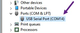 You will need a USB-A to RS232 cable to connect a Windows computer with
the rotator IR interface, for example the one pictured on the left.2You
could make your own, as I have done in the past, but it is probably
better to purchase one ready-made. They are not expensive. Plug the
cable
into a USB port—No need to connect the DB9 (RS232) end. A USB-to-serial
(FTDI) chip is built into the cable. Now start Device Manager on the
Windows machine and observe that Windows has assigned a COM port number
to the serial device in the cable (example illustration right).
If you have multiple active COM ports, unplug and plug-in the cable in
order to ascertain which COM port assignment belongs to the FTDI
device. Make a mental note of the number or jot it down.
You will need a USB-A to RS232 cable to connect a Windows computer with
the rotator IR interface, for example the one pictured on the left.2You
could make your own, as I have done in the past, but it is probably
better to purchase one ready-made. They are not expensive. Plug the
cable
into a USB port—No need to connect the DB9 (RS232) end. A USB-to-serial
(FTDI) chip is built into the cable. Now start Device Manager on the
Windows machine and observe that Windows has assigned a COM port number
to the serial device in the cable (example illustration right).
If you have multiple active COM ports, unplug and plug-in the cable in
order to ascertain which COM port assignment belongs to the FTDI
device. Make a mental note of the number or jot it down.
You will also need a DDE client. I downloaded and
installed the WiSP DDE Client (version 4.3) from this page. Key steps in the following paragraphs
refer to this specific DDE message receiver/parser.
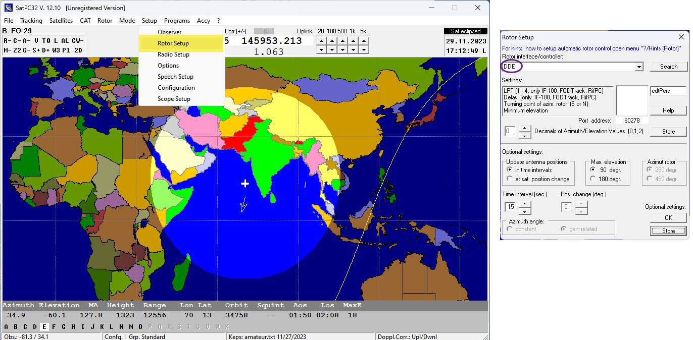
From the SatPC32 main menu bar select ‘Setup’ and
then ‘Rotor Setup’. In the Rotor Setup dialog, choose DDE from the
Rotor interface/controller drop-down list. Accept defaults for the
remaining configurable values and store the setup. That’s all there is
to the server side of the interface setup.
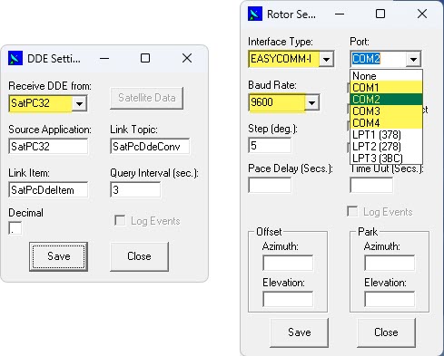
From the WiSP DDE client’s main ‘Settings’ menu
first select ‘DDE Link’ (left illustration above) and then choose
SatPC32 from the drop-down list. Remaining fields should
default to the values shown. If not, make it so. Store and close this
dialog. You may notice that WiSP reports ** NO SATELLITE **. Unless a
pass is in progress for whatever satellite has been selected in
SatPC32, this message is normal. In fact it is good, as it proves WiSP
is receiving the DDE broadcast from SatPC32.
Next from the WiSP ‘Settings’ menu select
‘Rotor’ (right
illustration above). From the ‘Interface Type’ drop-down list choose
EASYCOMM-1. That is the obvious part. Next proceed to the Port
drop-down list. Notice that there are just four selectable COM port
values COM1 through COM4. It is unlikely that Windows has associated
one of these numbers with the FTDI chip. Generally the virtual COM port
assignment will have been a larger number, such as the COM14
example from
my Windows 11 computer. Make sure that the COM number you choose in the
Rotor Setup is not already in use. In the above illustration I have
selected COM2. Finally set the data rate (BAUD) to the value 9600 if it
is not already so.
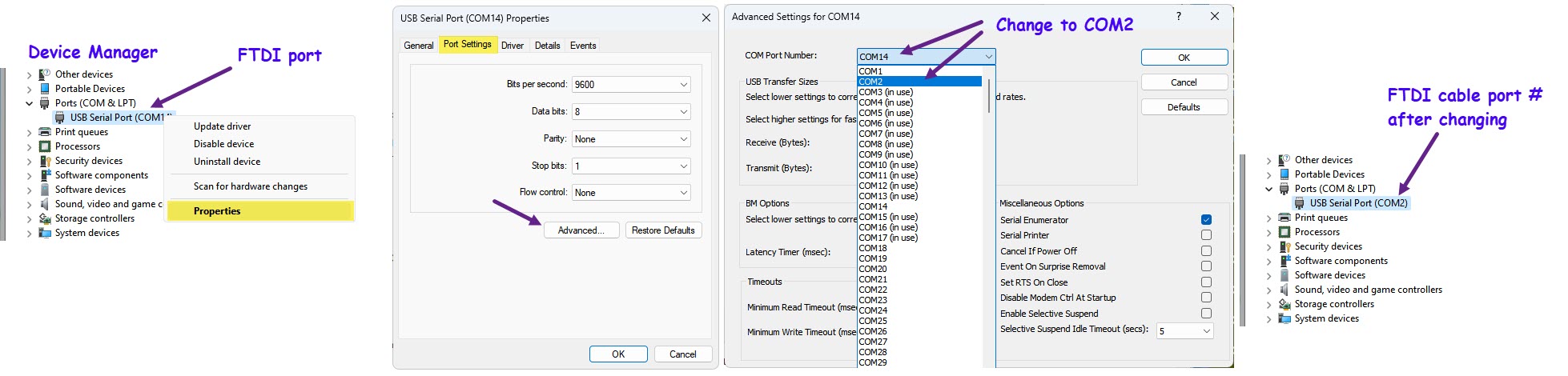
This is where things get interesting. In order to
channel WiSP’s EASYCOMM-1 formatted output to the FTDI cable we will
change the cable’s COM port assignment from the original number (COM14
in the example) to the port that was selected in WiSP (COM2 in the
example). Plug-in the USB-to-RS232 cable if it is not already plugged
in. Open Windows Device Manager, right click the cable’s entry and
choose ‘Properties’ (leftmost illustration above). In the Properties
dialog select the ‘Port Settings’ tab and in that dialog click the
‘Advanced’ button (second illustration from left,
above).
In the ‘Advanced Settings’ dialog change the COM
Port Number from its originally assigned value to the port number that
was specified in WiSP. In the illustrated example, COM14 is changed to
COM2 (second from right above). After accepting the change, observe
that Device Manager now refers to the USB Serial (FTDI) Port by the
number that was specified for WiSP output (rightmost illustration
above). This completes the software setup for the SatPC32 to Azimuth
controller interface.
 The RS232-to-TTL adapter used in the
antenna (IR) interface (this one from Amazon)
has silk-screened arrows
that indicate the data-flow direction of TTL pins. That is such a
great idea, certainly easier to interpret than ‘transmit’ / ‘receive’
markings would be. Thus it is obvious which pin should be jumpered
to the microcontroller’s serial input pin (GPIO47).
The RS232-to-TTL adapter used in the
antenna (IR) interface (this one from Amazon)
has silk-screened arrows
that indicate the data-flow direction of TTL pins. That is such a
great idea, certainly easier to interpret than ‘transmit’ / ‘receive’
markings would be. Thus it is obvious which pin should be jumpered
to the microcontroller’s serial input pin (GPIO47).
I normally use
‘Sats Helper’ as the azimuth data source for radio operations, and have
installed a DIP switch to enable the DB9
connector as the input for
testing with SatPC32. It is only necessary to plug or unplug ‘Sats
Helper’ from the 3.5 mm jack and toggle the DIP switch to change the
source.
Addendum 2: Many ham radio antenna rotators boast a range of
450°. Such a range allows rotating clockwise past 360° or counterclockwise past
0°. The RCA TV antenna rotator does not need this feature when used in its
intended application. However, during a subset of
ham radio satellite passes the satellite’s path crosses 0
degrees, and when it does the antenna rotator has to perform a full
rotation in the opposite to its previous direction, consuming nearly a
minute of time. During this time the azimuth continues to
change, sometimes quite rapidly. To avoid overshooting this moving
target, the controller interface (as revised) first rotates to 180°.
At this point it wipes any queued azimuth updates and waits for a new
one (on average half the interval between updates, e.g. a couple of
seconds). Upon receiving a fresh azimuth message the controller interface first rotates to the 30-degree
multiple that is closest to the received value, and then adjusts to the target azimuth.
In addition to the change described in the preceding
paragraph revision 1.1
of the interface incorporates other small improvements. Source comments
and debug statements convey more detail about how the interface
processes
azimuth messages in all contexts.
1. IRremote by shirriff, version 4.2.0.
2. Unless your computer has a hardware serial port. Newer
appliance computers do not generally have such ports.
Project descriptions
on this page are intended for entertainment only.
The author makes no claim as to the accuracy or completeness of the
information presented. In no event will the author be liable for any
damages, lost effort, inability to carry out a similar project, or
to reproduce a claimed result, or anything else relating to a decision
to
use the information on this page.