RF
Voltmeter
Autoranging: Over the years I have owned and used a
variety of
volt-ohm meters (VOMs), including
the famous ‘free’ one from
Harbor Freight.
Most had separate switch settings for measuring AC volts and DC volts,
and separate measurement ranges, such as 0 to 10 volts, 10 to 100
volts, 100 to 1000 volts, etc. All that has gone by the wayside. Now
there is one switch setting for volts, or perhaps volts and ohms. It is
not necessary to specify AC or DC, or a measurement range. The meter
automatically adjusts from millivolts to hundreds of volts, displaying
the measurement to 3 or 4 digits precision. Autoranging meters such as
my Mustool MDS8207 respond almost instantaneously.
Their ranging circuitry is electronic and evidently foolproof, or
nearly so.
I wanted to have a go at the auto-ranging concept,
but at a simpler or cruder level, so I thought of making an RF
voltmeter that would switch ranges automatically, depending on the
input level being
tested. This page describes the project that resulted. The ‘RF
Voltmeter’ is nothing more than an RF rectifier combined with a
microcontroller-based DC
meter. The boilerplate half-wave RF rectifier sub-circuit can be found
on multiple
Internet pages. It consists of a Schottky rectifier diode, with minimal
filtering / smoothing, as shown in the pictorial diagram above (bottom
middle). The DC measurement part of the meter consists of a
3-stage voltage divider for implementing the ranges, and an
ESP-12F development board. I had bought a ten-pack of these boards for
about $25 (Amazon),
without having a project in mind, rather just to see
what could be done with them. Previously I had experimented with other
NodeMCU boards, as well as with the amazing M5StickC-Plus.
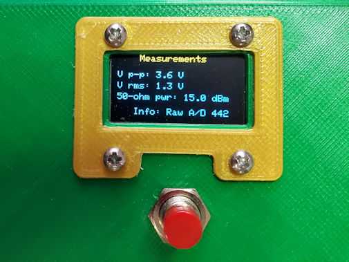
The RF voltmeter does not measure continuously.
To trigger a
measurement it is necessary to push the (momentary) button. For the display I used
a 0.96-inch monochrome OLED, because one was on-hand. There’s
not much information to display with a voltmeter, so a small screen
suffices. The display remains
on for 10 seconds (configurable) and then goes dark. I have learned
from my mistake of leaving OLED displays on for a protracted time.
When the button is pressed, A/D values are read ten
times (another configurable number) at 1/100 the DC input voltage. If
the average reading falls below a specified threshold, the range
changes to 1/10
the input voltage and the same test is applied. If the average A/D is
still less than the specified threshold the meter switches to 1:1 and
measures
the rectified raw applied voltage. Thus the meter has a working range
of one or two hundred millivolts to about 300 volts DC. However, the
rectifier does not have a
comparable range. The 1N5711 diode datasheet states that
its peak inverse voltage is 70—the specific capacitors used for the
prototype build have a somewhat higher
voltage rating. In addition to using higher voltage components for
the rectifier, it would also be advisable to pay attention to physical
layout, if it is desired to increase the RF measurement range.

Two small 3-volt relays, labeled
k1 and k2 in the image above,
are used to switch between
ranges. A couple of
LED’s were connected to the unused side of the DPDT relays for
debugging, prior to applying voltage to the A/D input of the ESP-12F.
The LED’s serve no useful purpose in the finished unit; however, I
decided to leave them in place and make a couple of slits in the enclosure
front as
decoration.
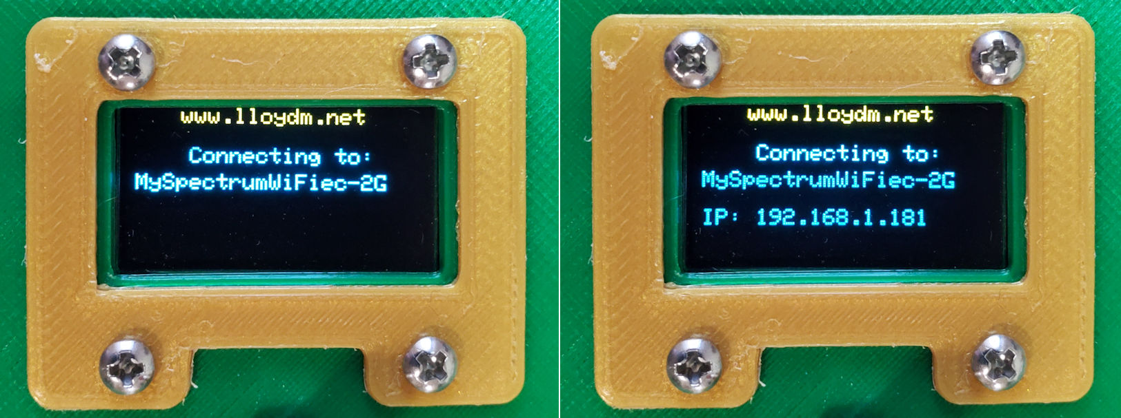
The ESP-12F is a WiFi board. After
assembling and calibrating the meter I added an optional UDP client to
the project sketch. There was a practical reason for this, namely to
include RF measurement parameters as part of a computer screen display for
demonstrating aspects of a different project. WiFi
parameters may either be included or omitted when
compiling the sketch. If the symbol
WIFI_SSID is not defined then the compiled application does not attempt
to
connect, or to implement the UDP add-on.
The sketch may be examined or downloaded here. To
compile it using the Arduino IDE (v.2), select NodeMCU 1.0
(ESP-12E Module) as the board. Various Internet sources state that the
12F board
is a minor revision of 12E, with an improved WiFi antenna being the
main or only change. Arduino compile and load functions work the same
for both boards. The top section of the sketch documents selectable
options, such as whether or not to
implement WiFi. A little further down are symbols for UDP IP and port.
These should be configured to match the UDP target. Additional
operational constants
are also configurable, as documented in Sketch comments.
Calibration:
There is more than one way to approach
calibration. I do not know whether different ESP-12F modules respond
more-or-less the same as one another in terms of their A/D conversion.
The two that I tested were virtually
identical. Both report a raw digital value of 9 or 10 when the analog
input
pin is grounded. Below about A/D = 12 displayed measurements should not
be fully trusted. The A/D ‘trust point’ is a configurable
constant named MIN_AD
in the sketch.
I used several different signal sources1 and
measurement methods2 to calibrate the
prototype unit described
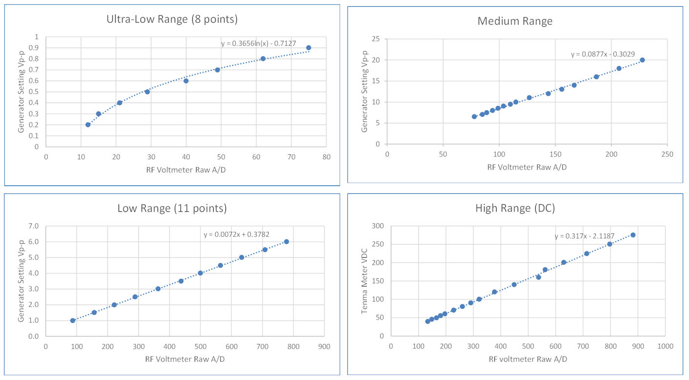
and illustrated on this page. A single regression equation sufficed for
each of the middle and high ranges. The low range was
linear above a certain point. Below that point it was
approximately logarithmic.
Thus two equations were derived from calibration data for
this range. In the sketch, the dividing point is a configurable
global constant
named NON_LINEAR_REGION, valued at A/D = 80 for the prototype. Below
this point a logarithmic fit is used and above it the fit is linear. The
high range was calibrated at the DC input point (rectifier disconnected) using a high voltage DC
power supply, and was not tested with an RF voltage source.
Although the ordinates are labeled
‘Generator Setting’ both low and medium range RF voltages were also
measured using the oscilloscope. As noted above, the rectifier was
bypassed when calibrating the high-range, and would not be useable
through most of that range unless higher
voltage-rated components were substituted.
Internally, high-range Vp-p is computed as 2 × the DC regression
equation.
1. Two function generators, a QRP transceiver, a couple
of batteries and DC power supplies.
2. Oscilloscope for HF and VHF, and bench voltmeter for
DC.
Project descriptions on this page are intended for entertainment only.
The author makes no claim as to the accuracy or completeness of the
information presented. In no event will the author be liable for any
damages, lost effort, inability to carry out a similar project, or to
reproduce a claimed result, or anything else relating to a decision to
use the information on this page.