Orbitron to
SDRuno Interface:
Why
interface Orbitron and
SDRuno? I started this exercise because I could not
find anything on Google about using Orbitron with SDRuno. It soon
became clear why this was
not a common or documented interface. The reason is
that for interfacing with other applications SDRuno uses
the CAT protocol (‘computer aided
tuning’
or ‘computer
aided transceiver’), while
Orbitron relies on a different method or standard for communication with other processes or devices.
Present generation ham radio
transmitters,
receivers, and transceivers nearly always implement some flavor of
a bi-directional CAT
interface, with
feature-specific variations from rig to rig.
A source of possible
confusion is that the
term CAT is used in different ways. In
some contexts CAT
may refer to hardware, such as specialized interface devices or
connectors. However, as
the term’s
meaning has evolved, it most
commonly describes the
structure
and content
of messages that pass between a computer and radio equipment.
As a messaging protocol CAT does not assert a transmission layer,
although in practice the latter is typically some relative
of the now more than 50
year old RS232 standard.
—Yes,
serial COM
ports (fondly remembered from the back panels of 1980’s
PCs) linger on in the radio world, although in today’s devices they are
more often virtual than physical.
I
apologize
if parts of this account are ‘overkill’. I
want to describe all
components of the hookup, even the obvious. Otherwise, some essential
part might be inadvertently omitted. First the main applications: 1. Orbitron
is the satellite tracking program shown in the lower right of the big
illustration at the top. It is widely used and popular for controlling
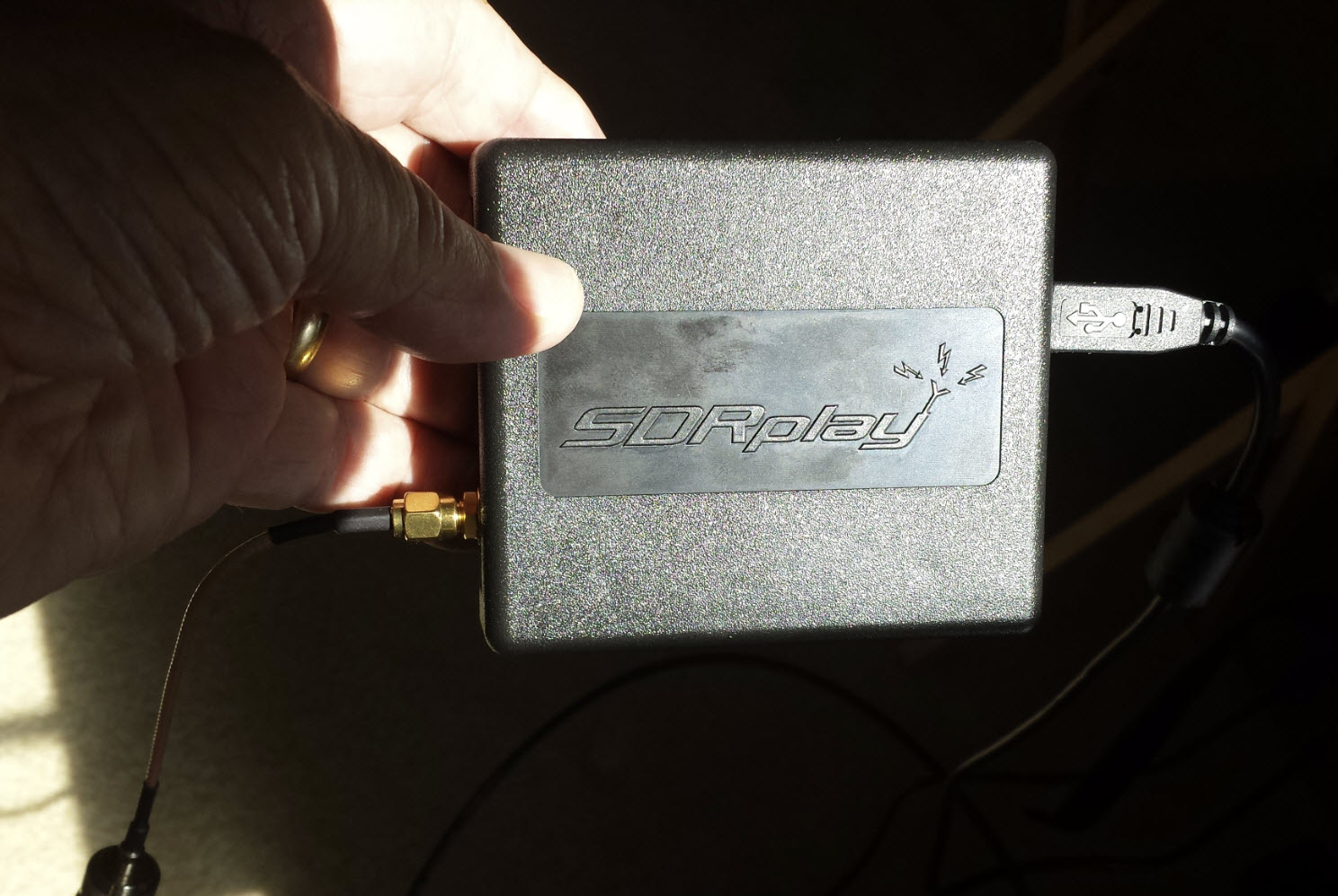
satellite receivers or antennas, and I think also small telescopes. 2. SDRuno
came to my attention
after I had purchased an SDRplay model RSP1A (https://www.sdrplay.com/,
photo
above). Previously
I had experimented with
other SDR applications: CubicSDR,
HDSDR,
SDRConsole,
and SDRSharp (software)
along with several
RTL-SDR dongles (hardware). However,
the SDRuno
application was specifically recommended for use with SDRplay, and an
immediate appeal of SDRuno is that
its software distribution includes
drivers for SDRplay.1
 Software
components of the present demonstration are
installed on a
Windows 10 laptop, loaned for the project. It is a
killer machine with 64 GB of RAM and a 4K screen. Actually the latter
can be a nuisance, as some programs, including a few that I have
written
myself, do not display correctly. Text that is too small can be made
larger, but not
buttons and such, but this display problem had no effect on the
present project.
Software
components of the present demonstration are
installed on a
Windows 10 laptop, loaned for the project. It is a
killer machine with 64 GB of RAM and a 4K screen. Actually the latter
can be a nuisance, as some programs, including a few that I have
written
myself, do not display correctly. Text that is too small can be made
larger, but not
buttons and such, but this display problem had no effect on the
present project.
It is not surprising that a 2016-vintage Laptop would not have any
physical COM ports. No matter, there are many ways to define
virtual COM ports under Windows. The software that I used is called com0com.
I do not recall whether the specific virtual port pair shown in the
image on the left were program defaults, or whether I picked those
numbers. Any
ports that are not in use will do, although I would incline
toward smaller numbers, as several Internet sources have
recommended.
The virtual pair is connected in a ‘null modem’ configuration (color
diagram), same as a null modem cable
between two physical ports.
Another useful utility (although not
needed or used in the interface) is a program called SerialMon.
By the way, all software used in this demonstration is free. I was
tempted to purchase some high grade analysis software, but the
main project as
summarized in
these paragraphs involves
only free applications and
utilities.
SerialMon
can be configured as a COM port sniffer, capturing everything that is
sent or received. This is exceedingly helpful for understanding how
communication between reference applications works. At one point in the
analysis stage of this project I
used a terminal emulator program (Termite)
to capture COM data from one of the two ports. However, with SerialMon
it is
possible to capture data from both ports as they communicate
bi-directionally. Just to be clear, though, neither SerialMon nor
Termite are
needed or used in interfacing Orbitron to SDRuno. They are simply tools
that may be helpful in analysis or debugging of serial communications.
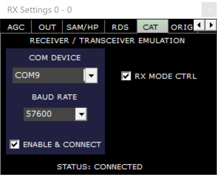 Pressing the
‘Sett.’
button in the SDRuno RX CONTROL form (or panel) opens a tabbed dialog
box (left). SDRuno
connects
to one of the [virtual] COM ports. Parameters
are entered under the CAT tab, as shown in the illustration. I have
read that the SDRuno serial port connection is fragile,
or that it has to be re-enabled at program startup, and in a particular
order. That may have been true of a different version or application
context. However,
I have not observed this behavior. Once enabled the connection is
automatically re-enabled when SDRuno is started. It does not matter if
the ‘Play’
button (in the MAIN form) has been pressed or is stopped.
Pressing the
‘Sett.’
button in the SDRuno RX CONTROL form (or panel) opens a tabbed dialog
box (left). SDRuno
connects
to one of the [virtual] COM ports. Parameters
are entered under the CAT tab, as shown in the illustration. I have
read that the SDRuno serial port connection is fragile,
or that it has to be re-enabled at program startup, and in a particular
order. That may have been true of a different version or application
context. However,
I have not observed this behavior. Once enabled the connection is
automatically re-enabled when SDRuno is started. It does not matter if
the ‘Play’
button (in the MAIN form) has been pressed or is stopped.
Now to the novel part, an obscure
middleware utility called DDEOrbitronToSerial: From its
description this utility appears to have been a ‘one-off’ that the
author (Alex) decided to share (Thank you!). This application should be
connected to the other COM port, the one that is not connected to
SDRuno. DDEOrbitronToSerial is a
DDE client (receiver of DDE messages) and a serial COM sender.
This program’s main form is shown in the lower left part of the
big illustration at the top of this write-up.
If DDEOrbitronToSerial
only forwarded DDE strings to a serial COM port exactly as they are
received, it
would not be serviceable to the present project. But the program’s
author also implemented
the ability to
extract and format DDE data before forwarding to the serial device.
When checked, the box called ‘Custom Format
String’ in the application GUI may define a string transform of DDE
input. (Strictly speaking the output does not have to reference DDE
data, but that would miss the point.)
As was previously noted, SDRuno does not
speak DDE. Like tabletop ham radio transceivers SDRuno uses CAT for
communicating. CAT
commands number in the hundreds, and vary between
implementations. However, only one command matters in the present
demonstration’s context, namely the one that requests the transceiver
(or in this case
SDR) to tune
to a specified frequency. (I am simplifying this description somewhat.)
Current generation radios typically have two or more tuners (VFOs) or
in some cases more than one
receiver. This project deals only with SDRuno’s primary receiver Rx0,
and its VFO-A. The CAT command to set VFO-A is simply FA + the
frequency and then semicolon. (CAT commands are terminated by
a semicolon.)
Radio frequencies range from long
wave
to the microwave spectrum and are specified in Hertz. In my first
attempt to get this interface working
I sent FA + frequency in Hertz as a canonic value + semicolon. That did
not work. In the CAT world, frequency is an 11-digit fixed-length
field, long
enough to specify any frequency below 100 GHz. For CAT it is necessary
to pad frequencies lower than 10 GHz with one or more leading zeros, in
order to
fill out the expected 11-digit length. Thus 137.62 MHz would be
formatted as
00137620000 (Hz). The CAT command to set VFO-A to this example
frequency is ‘FA00137620000;’.
It is possible that the ‘FA’ command is not universally implemented,
although I think it
probably is. In any case, SDRuno is documented as being compatible with
the Kenwood
TS-440S or TS-480 CAT Reference. (See SDRuno User Manual section on
interfacing with Ham Radio Deluxe.)
Ideally, one would construct the
CAT frequency command string programmatically, based on the canonic length of the
source frequency in Hertz. However, DDEOrbitronToSerial does not have a
programmer interface (This is not a complaint!). Therefore,
it is necessary to make an assumption about the length of the frequency
string. For the VHF range (NOAA satellites, plus the 2 meter and 70
centimeter amateur radio satellites, etc.) the canonic length is always
9
digits. For tracking microwave satellites it could be 10 or 11 digits,
but that is of no concern in the current context. To convert a 9 digit
frequency to 11 digits it is only necessary to pad the frequency (on
the left) with
the string constant "00", which leads directly to the ‘Custom Format String’
FA00[DN]; (where [DN] is
the program-supported variable for the downlink frequency, as received
via DDE.
 According to the posted directions for using DDEOrbitronToSerial
it should be
possible to add this utility as a named driver, such that it appears in
the Orbitron Rotor/Radio Driver drop-down list. A long time ago I added
an SDRSharp driver. However, for some reason, I have not got this
construct to work with the DDEOrbitronToSerial client. As a workaround
I
start DDEOribtronToSerial.exe manually before enabling
Rotor/Radio control from Orbitron. The ‘Send to serial’
box may be left unchecked until DDE data are available.
If logging is
enabled along with ‘Send
to serial’,
and if there’s
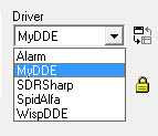
nothing to send, the log will record nuisance warnings. After starting
the DDEOrbitronToSerial
client, enable the ‘MyDDE’ driver from the Rotor/Radio
drop-down list. If
MyDDE has not yet been installed, the zip file download and
instructions may be found on the Orbitron
Downloads page. Starting
MyDDE will cause Orbitron to start sending DDE messages. (The
MyDDE
client will also start, but its form can be minimized or ignored.) Once
DDE messages are being received in DDEOrbitronToSerial, check the ‘Send
to serial’
box if not previously checked. If I
find out how to register DDEOrbitronToSerial
as a Rotor/Radio driver that starts DDE messages from Orbitron without
needing MyDDE, that will be an addendum to these notes.
According to the posted directions for using DDEOrbitronToSerial
it should be
possible to add this utility as a named driver, such that it appears in
the Orbitron Rotor/Radio Driver drop-down list. A long time ago I added
an SDRSharp driver. However, for some reason, I have not got this
construct to work with the DDEOrbitronToSerial client. As a workaround
I
start DDEOribtronToSerial.exe manually before enabling
Rotor/Radio control from Orbitron. The ‘Send to serial’
box may be left unchecked until DDE data are available.
If logging is
enabled along with ‘Send
to serial’,
and if there’s
nothing to send, the log will record nuisance warnings. After starting
the DDEOrbitronToSerial
client, enable the ‘MyDDE’ driver from the Rotor/Radio
drop-down list. If
MyDDE has not yet been installed, the zip file download and
instructions may be found on the Orbitron
Downloads page. Starting
MyDDE will cause Orbitron to start sending DDE messages. (The
MyDDE
client will also start, but its form can be minimized or ignored.) Once
DDE messages are being received in DDEOrbitronToSerial, check the ‘Send
to serial’
box if not previously checked. If I
find out how to register DDEOrbitronToSerial
as a Rotor/Radio driver that starts DDE messages from Orbitron without
needing MyDDE, that will be an addendum to these notes.
To summarize the above, assuming that
applications and accessories described
in the preceding paragraphs have been successfully installed, and that
either physical or virtual COM ports exist and are connected, and
finally that the serial channel is appropriately
configured for communication between DDEOrbitronToSerial and SDRuno,
the step-by-step procedure for implementing Orbitron-sourced Doppler
frequency
tracking in SDRuno is as follows:
1) Start up Orbitron and SDRuno (order
doesn’t
matter).
2) In Orbitron select the satellite that
you want to track.
3)
Start DDEOrbitronToSerial.exe (this is a concession to not having this
utility on Orbitron’s rotor/radio driver list).
4) If this is the first time, enter a
Custom Format String to construct the CAT command for setting downlink
(Doppler corrected) frequency, as has been illustrated above. The
Custom Format String and other utility settings will be saved
automatically in an XML file, and only need to be entered once.
5) When ready to start tracking, select
MyDDE from the Orbitron driver drop-downs and start it (button press).
The client form may be minimized, as it is not used. If not already
enabled, check ‘Send to serial’ in the DDEOrbitronToSerial client
window.
6) The rest depends on the
broader application context, which satellite is being tracked, its
transmission mode, etc. The video demo accompanying this write-up
features the WXtoImg application, which decodes
a NOAA VHF satellite transmission (NOAA-15, NOAA-18, or NOAA-19), and
renders a pleasing weather map image.
 Disclaimers:
First
it is not
necessary to process Doppler effect frequency
adjustments in order to receive and
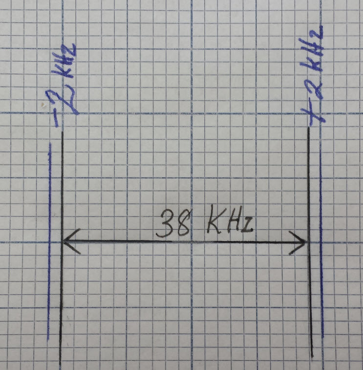
decode NOAA VHF weather images (as featured in the video demo).
These satellites transmit an FM signal that is about 38 KHz wide,
whereas their maximum Doppler frequency shift is only
± 2.something KHz. On the other hand, Doppler frequency corrections are
needed for orbiting satellites when they are transmitting narrowband
modes, such as SSB or telemetry or, for example, the July 2017
International Space Station Ham
Radio Anniversary images. Second,
alternative setups can be used for
Doppler frequency tracking when it is needed. I have previously used
Orbitron
with SDRSharp for this purpose,
and have also exercised Ham Radio Deluxe with
SDRuno
as well as with traditional tabletop radio equipment.2
Disclaimers:
First
it is not
necessary to process Doppler effect frequency
adjustments in order to receive and
decode NOAA VHF weather images (as featured in the video demo).
These satellites transmit an FM signal that is about 38 KHz wide,
whereas their maximum Doppler frequency shift is only
± 2.something KHz. On the other hand, Doppler frequency corrections are
needed for orbiting satellites when they are transmitting narrowband
modes, such as SSB or telemetry or, for example, the July 2017
International Space Station Ham
Radio Anniversary images. Second,
alternative setups can be used for
Doppler frequency tracking when it is needed. I have previously used
Orbitron
with SDRSharp for this purpose,
and have also exercised Ham Radio Deluxe with
SDRuno
as well as with traditional tabletop radio equipment.2
Demo:
OrbitronToSDRuno.mp4
Notes
1
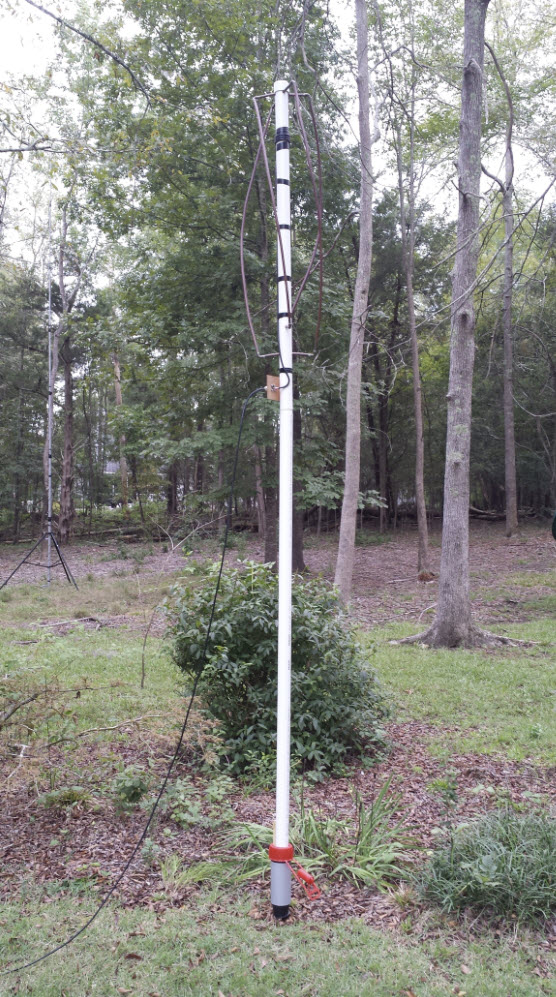
The
receiving antenna that is connected to SDRplay for NOAA VHF satellite
reception (video demo) is
a homebrew Quadrifilar Helix. As
shown in the photo below, this antenna is presently mounted on a 6
foot length of 2-inch PVC
in the back yard,
about 150 feet distant from the SDRplay. (In the future I may move it
to
the roof peak for a less obstructed view of the northern horizon.)
2
What’s in a name?—should pre-SDR radios be called ‘chip and solder’
rigs, or maybe Hardware
Defined Radios (HDRs)?
Surely they do not deserve the pejorative ‘legacy’ label.
Project descriptions on this page are intended for entertainment only.
The author makes no claim as to the accuracy or completeness of the
information presented. In no event will the author be liable for any
damages, lost effort, inability to carry out a similar project, or to
reproduce a claimed result, or anything else relating to a decision to
use the information on this page.