In truth...
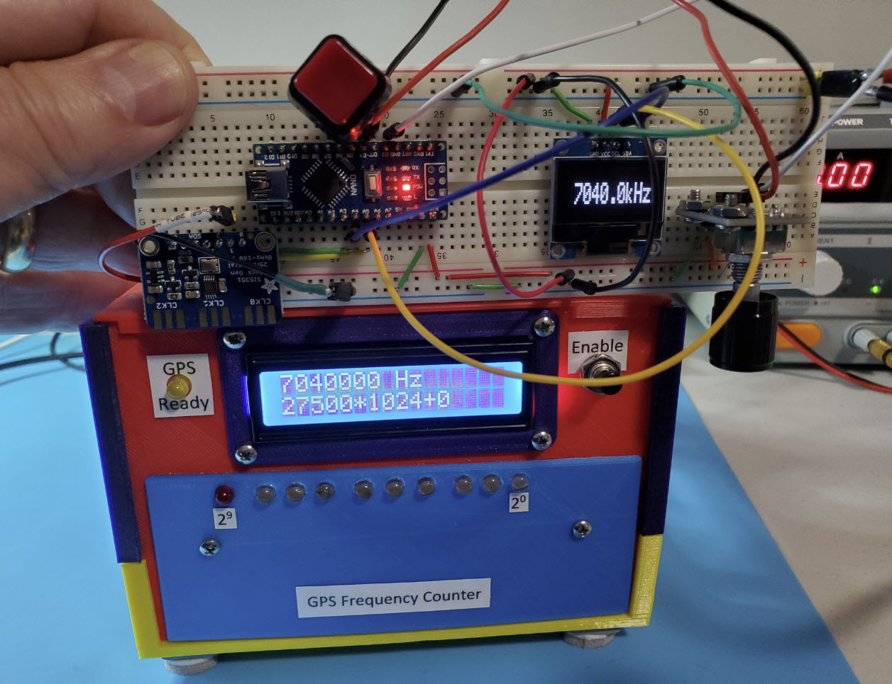
The frequency counter more often displayed 7039999.25 Hz or 7040000.5
Hz or
etc., but from time to time the Si5351’s output measured dead-on the
programmed frequency to the nearest whole cycle at 7040 KHz, as shown
in the photo. Moreover, after being
powered-on for a short while the clock generator
stayed within a few Hz of the programmed frequency from 3.5 to 30 MHz
(80 to 10 meters). The following paragraphs describe the rationale and
implementation of a simple and logical Si5351 frequency correction
method.
Popular
chip: The Si5351 is ubiquitous. Several ham radio kits and
other projects that I have written about have featured
this clock generator or the Si5351A (e.g., Hilltopper, QCX, Quadrature
VFO, μBITx). The chip is also found
in a few familiar manufactured products (e.g., Elecraft KX2, NanoVNA).
On reading or skimming articles and web pages about Si5351-based signal
generators or VFO’s or other projects, I have been surprised at the
number of different ways that frequency control is implemented. In
part the diversity of approaches can be understood in relation to the
context and period of the project described, or whether an Si5351
library was utilized, or the type of microcontroller that interfaces
with the clock generator, etc. It is also curious that Si5351-based
projects implement frequency correction
in a variety of different ways.
 An article in December 2020 QST
magazine1
(the current issue as I write) put in mind to revisit Si5351 frequency
programming and correction. The article describes a
milliwatts power CW
transmitter based on the Si5351. Minimum tuning step is 100 Hz, a
workable value for a CW QRP rig. And to correct the generated clock
frequency
a constant is added-to or subtracted-from the selected (dialed) output
frequency before computing Si5351 programming parameters.
An article in December 2020 QST
magazine1
(the current issue as I write) put in mind to revisit Si5351 frequency
programming and correction. The article describes a
milliwatts power CW
transmitter based on the Si5351. Minimum tuning step is 100 Hz, a
workable value for a CW QRP rig. And to correct the generated clock
frequency
a constant is added-to or subtracted-from the selected (dialed) output
frequency before computing Si5351 programming parameters.
Although adding a correction to the output frequency is common in
Si5351 radio projects, the method seems a little off conceptually. It
is natural to ask, “What part
of frequency determination needs correction?” Output clock frequency is
programmed in the Si5351 using
parameters that ultimately depend on an external crystal frequency.
Every Si5351 generated frequency depends on this reference frequency in
more-or-less the
same way. VCO frequency is
a multiple of the crystal oscillator frequency and this dependency
carries through the process of dividing VCO frequency to
obtain a desired output.
At the risk of ‘beating a dead horse’
the crystal that provides a reference frequency for the Si5351 has a marked value (photo
left),
and under suitable conditions an acceptably stable true
value. The discrepancy between marked and true frequency of the crystal
oscillator accounts for the error in output frequency. This observation
applies to both of the Si5351’s synthesizers, and across the
spectrum of frequencies to be generated. An obvious corollary is that
if the crystal’s true frequency were specified in place of the
marked frequency everywhere that the reference frequency appears in a
calculation (generally just one place per clock), then derived
frequencies (clock
output frequencies) would be correct to within the stability of the
circuit. The ‘Correcting Frequency’ section below elaborates this idea,
but first...
Programming
frequency:
An Internet search yields many helpful examples of programming the
Si5351, either with or without the help of Arduino libraries (si5351.h
or Adafruit_SI5351.h). One
particularly readable explanation is this
page,
which presents an easy to follow computational recipe or algorithm for
generating clock output frequencies. There is a ‘shortcut’, where the
largest allowable denominator (220 - 1) is used
in solving for
a fraction to represent a decimal computed value. (Si5351 decimal
valued parameters must be specified in the form whole number +
numerator / denominator.) I have experimented a little
with another way of generating
good fractions, and also with Silicon Laboratories ClockBuilder Desktop
utility. However, one obvious virtue of a fixed denominator is
simplicity. No messing around, just solve for the numerator. Using the
same denominator in multiple computations is also fast, which could be
important, as many Si5351 applications are based on an Arduino Uno or
Nano, or other similarly slow MPU platforms—not well suited to
computation.
Correcting
frequency:
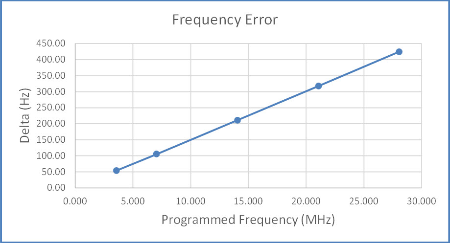
Graphs are nice, but in this case not necessary. A single data point
suffices to compute the actual ‘crystal oscillator frequency’
and hence the required correction. For this computation it is not
necessary to know how
Si5351 parameters were computed or specified, i.e., how the clock
output frequency was derived. To illustrate, select a point on the
graph that is close to the crystal’s
25 MHz marked frequency.
When the Si5351 was programmed to produce an
output frequency of
21060 KHz, the measured frequency before correction was 21,059,682.5 Hz
or 317.5 Hz below the programmed frequency (4th
point from left on graph). Now, 21060000 Hz is 25 MHz
multiplied
by 0.8424 regardless of the particular Si5351 parameters used to
produce this output. Therefore, we can immediately compute the
putative reference frequency (i.e., the true frequency of the
crystal oscillator) by dividing the measured frequency by 0.8424. This
calculation yields 24,999,623 Hz, or 377 Hz below 25 MHz.
Substituting this value for the marked frequency
in whatever algorithm is used to setup the PLL and perform the division
(or divisions) should cause the clock output frequency to be very
nearly exact across the application’s programming range.
It is a matter of style as to how to implement this simple correction
in code. Generally, constant declarations are listed near the top of
a program (or Arduino sketch), and in uppercase. This is
convenient when, for example, the value of the constant needs to be
revised for a different circuit than the one originally studied.
How precise is the Si5351 after correction? I have not examined this
question over the long term, but for one day of repeated observations,
the corrected clock frequency remained within 1 part per million from
true (as measured by the GPS-referenced frequency counter)
across the range 3.5 to 30 MHz. Again on the following day,
measurements remained within the previously observed delta after
warmup.
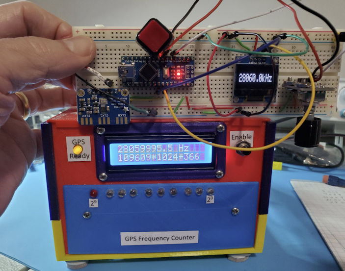 Less than
1-PPM error at 28 MHz
Less than
1-PPM error at 28 MHz
1. The Tuna Tin “S” — A
Bare-Bones Synthesized QRPp Transmitter, by Bob Fontana, AK3Y.
QST
December 2020, Vol 104, Number 12, pp 30-35.
Project descriptions on this page are intended for entertainment only.
The author makes no claim as to the accuracy or completeness of the
information presented. In no event will the author be liable for any
damages, lost effort, inability to carry out a similar project, or to
reproduce a claimed result, or anything else relating to a decision to
use the information on this page.