 1.
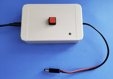
On-off
switch for power brick: Nothing is simpler than an on-off
switch, yet most power bricks, chargers, and the like do not have a
switch. This is of no consequence if you are charging your phone, but
what if you are powering a Raspberry Pi—or
a project breadboard. It
would be nice, not to
have to pull the plug when cycling power. Of course there are
countless ways to add a switch. I prefer a latching pushbutton on the
enclosure top for two reasons: First, I have a bunch of them, and
second, switching by pushing down from on-top does not cause the nearly
empty
enclosure to tip over. The
switch’s input and output connections can be as
simple
as cutting and splicing the power supply’s DC wire. If the parts
bin includes DC power plugs and jacks, consider making the switch box
pluggable. Similarly, an LED
indicator (lower-right in photo) enhances the setup.
1.
On-off
switch for power brick: Nothing is simpler than an on-off
switch, yet most power bricks, chargers, and the like do not have a
switch. This is of no consequence if you are charging your phone, but
what if you are powering a Raspberry Pi—or
a project breadboard. It
would be nice, not to
have to pull the plug when cycling power. Of course there are
countless ways to add a switch. I prefer a latching pushbutton on the
enclosure top for two reasons: First, I have a bunch of them, and
second, switching by pushing down from on-top does not cause the nearly
empty
enclosure to tip over. The
switch’s input and output connections can be as
simple
as cutting and splicing the power supply’s DC wire. If the parts
bin includes DC power plugs and jacks, consider making the switch box
pluggable. Similarly, an LED
indicator (lower-right in photo) enhances the setup.
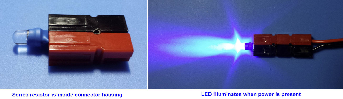
2. Indicator LEDs: I use Anderson Power Poles for everything 12 volt. These genderless connectors are ideally suited for connecting different rigs or devices to different power supplies, or for running the same rig in the house and car, etc. Sometimes you want to know if a voltage is present at one of these connectors. For example, you may not remember whether or not the cable was left connected to the car or boat battery, or was unplugged. A portable voltmeter works, but this pocket tester is handy, and may be conveniently stored with a supply of connector parts:
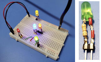 In
a similar vein, if you use breadboards for prototyping circuits, it can
be helpful to have one or two or a few pluggable LED’s for
quick-testing key circuit points. A variety of pin-header spacings
could be used. Be sure to mark polarity. I use the stripped ends from
plastic-insulated hookup wire to mark the plus side (heat shrink is no
good on bare wire).
In
a similar vein, if you use breadboards for prototyping circuits, it can
be helpful to have one or two or a few pluggable LED’s for
quick-testing key circuit points. A variety of pin-header spacings
could be used. Be sure to mark polarity. I use the stripped ends from
plastic-insulated hookup wire to mark the plus side (heat shrink is no
good on bare wire).Different color LED’s vary in brightness, blue being the brightest. I generally use 1000 ohms or more in series with blue LED’s, and 330 or 470 ohms (for current limiting) with dimmer colors.
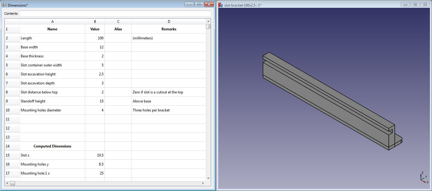
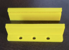
 3. Slot
Brackets: PCB’s and generic prototyping boards often have
very tiny corner mounting
holes—or if you cut the PCB’s as I do, no holes at all in some cut off
parts. An alternative
way to mount PCB’s in an enclosure or other framework is to use slotted
brackets, where the slot width matches the PCB thickness. This simple
application is one
of many good uses for a 3D printer. See also item 5 below.
3. Slot
Brackets: PCB’s and generic prototyping boards often have
very tiny corner mounting
holes—or if you cut the PCB’s as I do, no holes at all in some cut off
parts. An alternative
way to mount PCB’s in an enclosure or other framework is to use slotted
brackets, where the slot width matches the PCB thickness. This simple
application is one
of many good uses for a 3D printer. See also item 5 below.I use FreeCAD for custom designs. FreeCAD has a built-in spreadsheet option that can be used to specify the variable dimensions of a design, including computed dimensions. The latter could include, for example, the location of mounting holes as a function of the slot bracket’s lip length and width. Thus a single FreeCAD design can accommodate multiple PCB sizes and shapes. To print brackets for a different PCB simply change relevant dimensions in spreadsheet cells. It is not necessary to edit part properties directly as these just name the spreadsheet cells (or their aliases).
 4. Polarity-safe
PCB:
A few of the low power kits I have assembled include a diode in series
with the power connector. If you accidentally connect the 5 or 9 or 12
volt power supply backwards, nothing happens. The circuit doesn’t work
but neither does it transmit a smoke signal in place of the audio or RF
that was expected. I have wondered if substituting a full-wave
rectifier for the diode would not only prevent damage but also permit
the circuit to work, regardless of which way DC power input was
connected. I have not tried this, however I have used a different
scheme for powering circuit boards that ensures that power can only be
applied with the correct polarity.
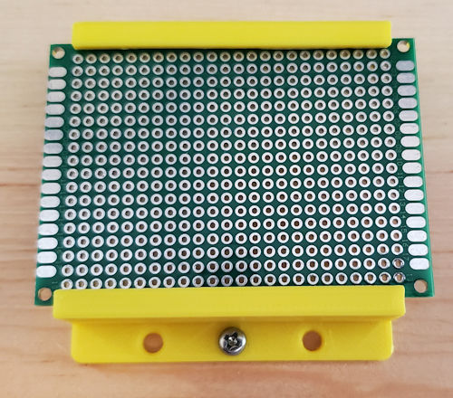
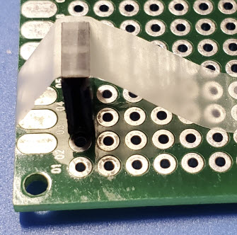
4. Polarity-safe
PCB:
A few of the low power kits I have assembled include a diode in series
with the power connector. If you accidentally connect the 5 or 9 or 12
volt power supply backwards, nothing happens. The circuit doesn’t work
but neither does it transmit a smoke signal in place of the audio or RF
that was expected. I have wondered if substituting a full-wave
rectifier for the diode would not only prevent damage but also permit
the circuit to work, regardless of which way DC power input was
connected. I have not tried this, however I have used a different
scheme for powering circuit boards that ensures that power can only be
applied with the correct polarity.In my projects power typically connects to pin headers on the circuit board. Two pins are needed for + and – but if only two pins are used, it is possible to accidently connect them backwards. This assumes ordinary pin headers, not a socket that only accepts one-way connections. The simple trick is to use three pins, making the middle one + and the two outer ones – (see photo). It is still possible to go wrong if the supply end does not also use a 3-pin (usually female) header. Obviously if only two pins are used on the supply side, it would still be possible to generate smoke signals.
 While on the subject of headers, I have a suggestion for soldering them
to PCBs. Male pins transfer heat effectively from the underside of the
PCB to the top where your finger might be if you haven’t previously
experienced the consequences of using a finger to hold the header.
Actually I have two suggestions for this. First, temporarily
insert the male pin header into a female header. A lot less heat will
reach the finger if holding the assembly by the edges of a female
header. Suggestion #2, use cellophane tape in place of a finger to
steady the assembly in approximately the desired orientation. When one
pin has been soldered, remove the tape and reheat the joint while
jiggling the assembly until it is solidly against the PCB with pins
properly aligned.
While on the subject of headers, I have a suggestion for soldering them
to PCBs. Male pins transfer heat effectively from the underside of the
PCB to the top where your finger might be if you haven’t previously
experienced the consequences of using a finger to hold the header.
Actually I have two suggestions for this. First, temporarily
insert the male pin header into a female header. A lot less heat will
reach the finger if holding the assembly by the edges of a female
header. Suggestion #2, use cellophane tape in place of a finger to
steady the assembly in approximately the desired orientation. When one
pin has been soldered, remove the tape and reheat the joint while
jiggling the assembly until it is solidly against the PCB with pins
properly aligned.Cellophane tape is better than a jig for many purposes. For example, suppose you want to solder a bare wire to use as a ground bus on the bottom of the board. One trick is to bend the wire ends up through holes temporarily, but that may not be feasible in every case. Equally effective is to tape the wire to the board until one part has been soldered, and the wire no longer wants to move about. I have also used cello tape to hold a DIP socket in place, or a crystal, or really anything that tends to move while in the process of being attached.
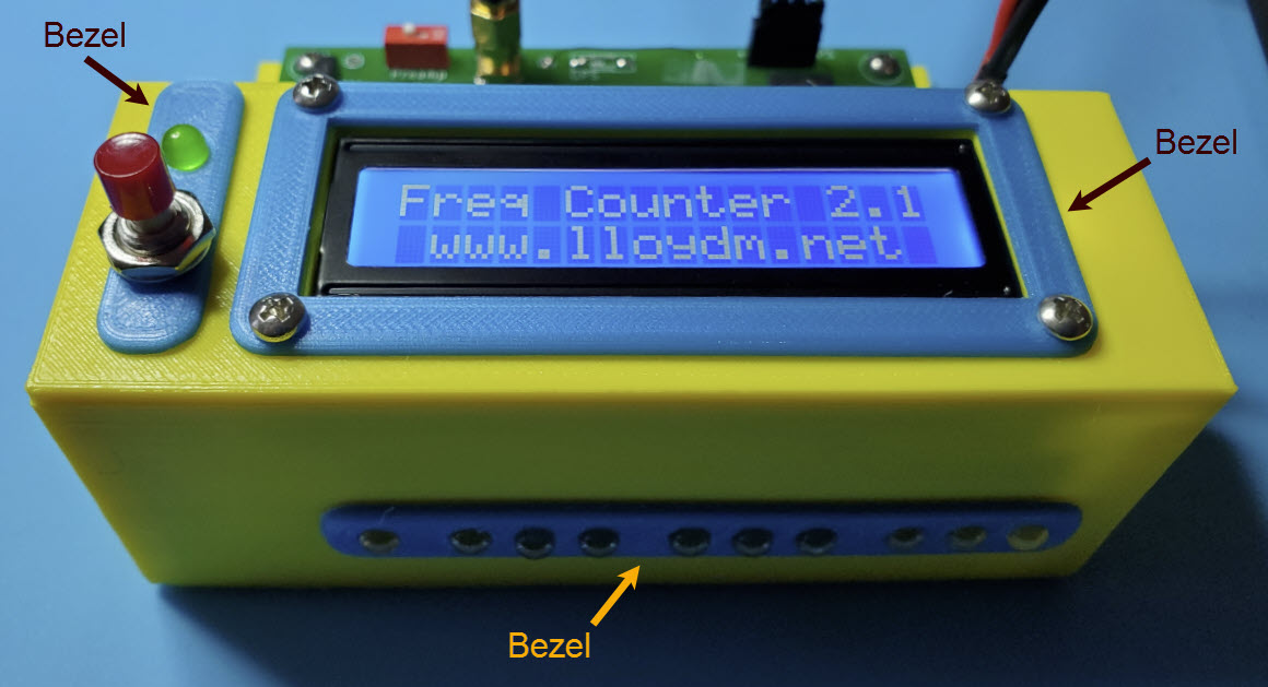
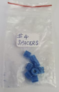 5.
Bezels
Beautify: Bezels are generally thin and flat and
make another ‘easy’ 3D-printer project. The
reward to investment ratio is good, although there comes a
point where beauty can morph into clutter.
5.
Bezels
Beautify: Bezels are generally thin and flat and
make another ‘easy’ 3D-printer project. The
reward to investment ratio is good, although there comes a
point where beauty can morph into clutter.As I think about it, there are many ‘easy’ things to do with a 3D-printer. The small spacers (left) are perfect for mounting a 16x2 LCD in a panel cutout. It takes only about 10 minutes to print a set of 4. As with the PCB mounting brackets, different diameters and lengths can be printed from a single graphical design, by editing one or two spreadsheet cells.
Of course 3D printers are not as common or inexpensive as soldering irons. Perhaps the hard part is to acquire a 3D printer and learn to make it work and, after that, to keep it working!
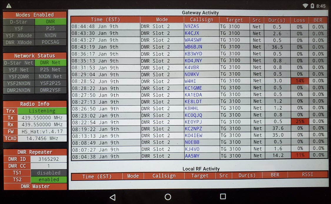
6. Repurposed Tablet: What to do with an old tablet? The battery is dead and cannot be replaced for less than the cost of a new tablet. One admittedly niche use is as a hotspot activity monitor. A browser (Chrome, in the illustration) connects to the MMDVM hotspot wirelessly. In my setup the Google Nexus tablet sits on the desk next to the radio. Of course, since its battery is dead the tablet has to be plugged in all the time. The screen is set to the dimmest level that is bright enough for daytime viewing. The screen is also configured not to timeout (sleep). In this configuration the tablet acts as a dedicated Gateway monitor. While it does not lose its connection to the hotspot, and the screen remains illuminated 24-7, I have not figured out how to keep the DMR gateway connection alive for more than one day, without transmitting briefly. (Problem solved—See footnote1) Nor have I thought how to make DMR over the Internet an interesting exercise! (Problem not solved) Seriously, though, the dedicated monitor concept can be applied in multiple ways, for example, to show APRS activity, or amateur radio satellites status, or high frequency propagation, or any sort of actively updated information.
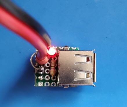 7.
USB adapter for bench power supply: Suppose you are working
on a microcontroller based project, say Arduino or Teensy or some other
platform. The project involves back-and-forth between a
software/firmware development platform, perhaps a desktop computer, and
the bench where the project’s hardware components are being assembled
and tested. It would be convenient to power the microcontroller from
the bench power supply, but at this stage the microcontroller wants a
USB cable connection, same as if it were being powered from the
development computer.
7.
USB adapter for bench power supply: Suppose you are working
on a microcontroller based project, say Arduino or Teensy or some other
platform. The project involves back-and-forth between a
software/firmware development platform, perhaps a desktop computer, and
the bench where the project’s hardware components are being assembled
and tested. It would be convenient to power the microcontroller from
the bench power supply, but at this stage the microcontroller wants a
USB cable connection, same as if it were being powered from the
development computer.A simple adapter for this purpose can be made using a USB-A female connector, as shown in the photo. The LED indicator is optional. On the bench (power-in) side, any sort of connection should work, provided polarity is observed, and the input is limited to 5 volts. My personal convention is to use a 3-pin male header, where the two outside pins are ground and the middle pin accepts +5 volts. The power supply cable terminates in a 3-pin female header, which can be plugged in either way, while ensuring that + goes to + and ground to ground (cf. paragraph 4 above).
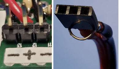
 8. Pin header cover:
As a general rule power or signal sources have female connectors
(sockets), while loads or signal consumers have male connectors (plugs). The
situation is more ambiguous in the small circuit construction context. A strip of male
pins may convey a mixture of signal types or directions.
All is well so long as a mating connector protects the pins from accidental contact with unrelated conductive components.
However, when not connected, the same pins are exposed to the chance of
accidental contact with, say, a metal shield or wire or touch (static discharge). Although the
circuit under construction may not involve high voltages, it is
possible that errant contact could damage a sensitive component,
such as a specialized integrated circuit.
8. Pin header cover:
As a general rule power or signal sources have female connectors
(sockets), while loads or signal consumers have male connectors (plugs). The
situation is more ambiguous in the small circuit construction context. A strip of male
pins may convey a mixture of signal types or directions.
All is well so long as a mating connector protects the pins from accidental contact with unrelated conductive components.
However, when not connected, the same pins are exposed to the chance of
accidental contact with, say, a metal shield or wire or touch (static discharge). Although the
circuit under construction may not involve high voltages, it is
possible that errant contact could damage a sensitive component,
such as a specialized integrated circuit.Pin headers are also used as jumpers, functionally the same as switches for selecting settings. In manufactured devices jumper pins are typically recessed and thus less susceptible to accidental shorting. In homebrew construction it is a good idea to cover unconnected pins, whatever their purpose. A simple and neat way to do this is to cut a matching size (mating) female pin-header, clip the solder tabs from the piece, and cover it with shrink wrap for easy identification (photo).
1. The disconnect problem turned out to be specific to Talkgroup 310. Upon switching to TG 3100 (as in the illustration) the Gateway Activity monitor no longer lost its connection in the wee hours. As of this writing it has remained connected for several weeks without having to goose the gateway to reconnect.
Project descriptions on this page are intended for entertainment only. The author makes no claim as to the accuracy or completeness of the information presented. In no event will the author be liable for any damages, lost effort, inability to carry out a similar project, or to reproduce a claimed result, or anything else relating to a decision to use the information on this page.