RF Field Strength Meter

 What is it?
A radio frequency (RF) field strength meter is like an S-meter for a
big chunk of the electromagnetic spectrum. The project described in the
following
paragraphs is an uncalibrated
meter. Readings are relative and the display range is adjustable. In
theory (and in advertisements) it is possible to measure antenna
radiation patterns using a relative field strength meter, and to
compare such observations to design-based
expectations. This exercise might work if there were no trees, houses,
fences, etc. in the way. Otherwise, it becomes rather difficult to
carry out. Another different sort of application called ‘fox hunting’
was
featured in a recent QST
article.1
The suggestion was that once the hunter (using a radio direction
finder) comes near enough to the fox (a hidden
radio
transmitter), a field strength meter can be used to zero-in on the
fox’s
exact
location. —Perhaps so.
What is it?
A radio frequency (RF) field strength meter is like an S-meter for a
big chunk of the electromagnetic spectrum. The project described in the
following
paragraphs is an uncalibrated
meter. Readings are relative and the display range is adjustable. In
theory (and in advertisements) it is possible to measure antenna
radiation patterns using a relative field strength meter, and to
compare such observations to design-based
expectations. This exercise might work if there were no trees, houses,
fences, etc. in the way. Otherwise, it becomes rather difficult to
carry out. Another different sort of application called ‘fox hunting’
was
featured in a recent QST
article.1
The suggestion was that once the hunter (using a radio direction
finder) comes near enough to the fox (a hidden
radio
transmitter), a field strength meter can be used to zero-in on the
fox’s
exact
location. —Perhaps so.
RF Exposure:
This topic is an odd mixture of hocus pocus (tinfoil hats,
cellphone
stickers, etc.) and genuine scientific concern or interest.
In regard to the latter, the US Federal Communications Commission (FCC)
has recently revised its rules for how amateur radio stations should
evaluate RF-exposure (ARRL FAQ). To be clear, the long
standing safe exposure limits themselves have not changed, just the
requirement as to how US licensed ham stations must evaluate compliance.
When they are required, RF-exposure
evaluations generally consist of making calculations from parameters
such as transmit power, frequency of transmission, transmit duty cycle,
and antenna gain. These calculations are made easier by the
use of an RF
Exposure Calculator. Direct measurement of RF fields is not
practical for this purpose, at least not with the type of relative
field strength meter
described on this page. Even with a
laboratory-grade calibrated instrument, direct assessment of RF
exposure would be a
formidable challenge (ARRL summary).
RF log
amplifier: A remark by a fellow ham about the
possibility of direct
measurement as
a means of compliance with the FCC RF-Exposure rule change sparked
my interest in RF field strength meters.2
I had previously experimented with an Analog Devices AD8318 RF log amplifier chip in an
unrelated context. Frequency bands that are designated
for amateur radio operation range across the electromagnetic spectrum
from
long-wave to microwave, all the way to visible light. However, the most
popular bands are located in the approximately
1 to 30 MHz (High Frequency or HF) part
of
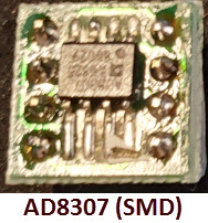
the spectrum. This makes the Analog
Devices AD8307 (100 KHz to 500 MHz) an appropriate choice for
the
detector part of a
general purpose relative field strength meter.
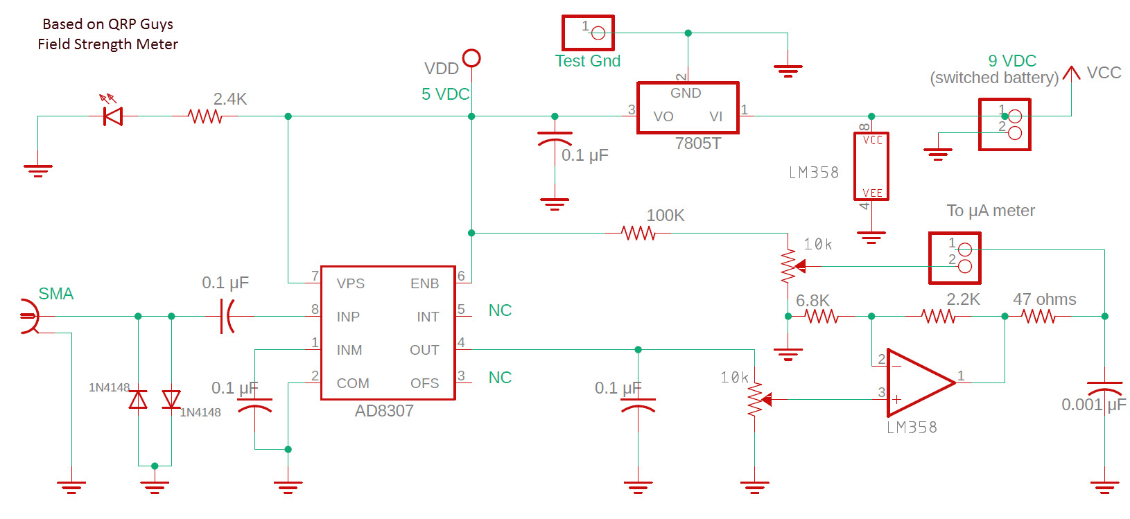
The AD8307 features in several amateur
construction circuits,
including one retired kit from QRPGuys,
as well as the aforementioned QST
project. The present
project (schematic
above) was chiefly based
on the QRPGuys design (schematic at the penultimate
page of the kit assembly manual). However, as
far
as I can
tell, relative field strength meter circuits are all very similar to
one
another, each consisting of a detector-log amplifier followed by an
additional amplification stage and some form of display. The detector
part is basically a boilerplate circuit from the AD8307 datasheet. An op
amp or common amplifier transistor circuit boosts the
RF chip’s log voltage output to a level suitable for
interfacing an analog or
digital display.
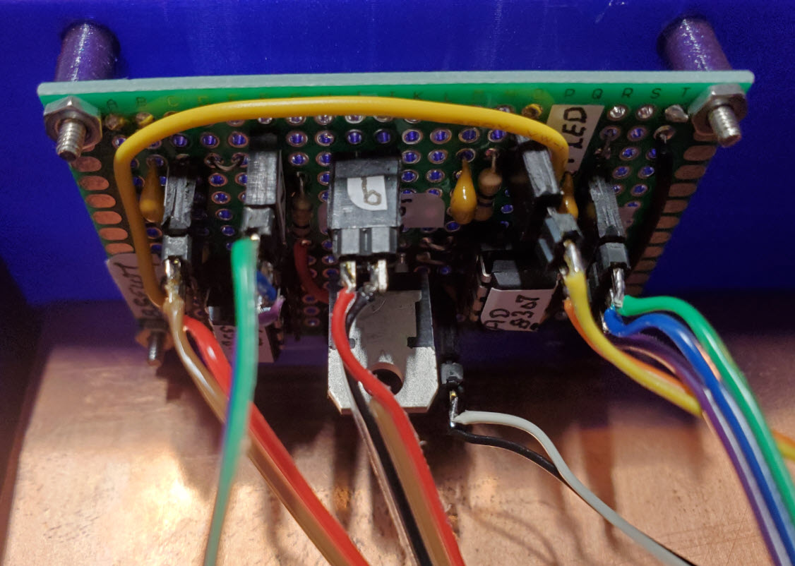
I should learn to make panel labels, or at
least to make room for
them! The top potentiometer (photo at top of page) is the gain control
and the one below it is for setting the zero level of the meter. RF
energy is
everywhere, so it makes sense to set the meter at some low non-zero
reading, to represent ambient RF (broad spectrum noise). The ‘zero’
potentiometer allows setting it
to any value on the scale. The amount of amplification needed depends
on
the sensitivity of the meter (or other display). One LM358 easily
drives a 200 μA meter.
It might be possible to arrive at some
physical interpretation of
readings by inserting RF attenuators. One could observe
and record changes in meter readings that correspond to different
attenuation
levels.
But I doubt this would be of much use, unless the meter were to be
calibrated for a specific narrow frequency band. Hint: Calibration is
not easy! This
article, for example, describes calibrating a field strength
meter for the 2200 meter amateur band.
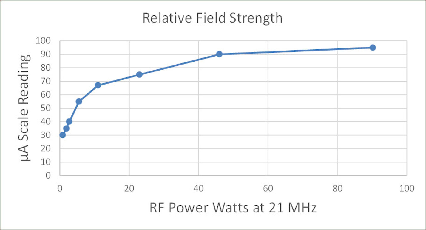 At the time the circuit for
this project was first assembled on
a breadboard3
I had not completely abandoned the idea of its usability for RF
exposure assessment. One exploratory exercise recorded relative RF
field strength (microammeter readings) for a sequence of test FT8
transmissions on the 15 meter ham band. Transmit power ranged
from 1 watt to nearly 100 watts. The backyard transmit antenna was
aimed approximately orthogonal to the field strength meter’s location
in the ham shack. For this ‘study’, gain and zero potentiometers were
pre-adjusted to
produce the range of meter deflections recorded.
At the time the circuit for
this project was first assembled on
a breadboard3
I had not completely abandoned the idea of its usability for RF
exposure assessment. One exploratory exercise recorded relative RF
field strength (microammeter readings) for a sequence of test FT8
transmissions on the 15 meter ham band. Transmit power ranged
from 1 watt to nearly 100 watts. The backyard transmit antenna was
aimed approximately orthogonal to the field strength meter’s location
in the ham shack. For this ‘study’, gain and zero potentiometers were
pre-adjusted to
produce the range of meter deflections recorded.
The trend depicted in the graph (left)
is systematic but
that doesn’t prove anything. Measurements (meter deflections) could not
be correlated with meaningful physical units. Moreover, the
‘rubber duck’ antenna
attached to the meter was designed for VHF use, a frequency range far
above the 15 meter band.
In fact, briefly triggering a 2-meter handheld transmitter in the next
room
causes the microammeter to go off-scale. —It is always possible,
of course, to bring the meter within scale, as the gain potentiometer
can
be turned all the way to 0, which grounds input to the amplifier.
 Enclosure:
3D-printed enclosures consume a lot of filament and print time.
By design the
enclosure bottom included a large rectangular
cutout that could be covered by a piece of copper. (See PCB
photo
above.) To prevent the possibility of accidentally shorting the meter,
an index card was taped to the copper on the inside before final
assembly. I had
thought of shielding the entire box. It would be fairly easy to cover a
3D-printed enclosure or sub-enclosure with adhesive copper tape, but that did
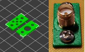
not seem necessary. One trick I
will mention: The SMA jack is a PCB mount type. To attach it to the
panel I made a two part adapter. The back part has holes for the center
conductor and four corner ground posts, while the front part has a
single hole
for the SMA female connector (right).
Enclosure:
3D-printed enclosures consume a lot of filament and print time.
By design the
enclosure bottom included a large rectangular
cutout that could be covered by a piece of copper. (See PCB
photo
above.) To prevent the possibility of accidentally shorting the meter,
an index card was taped to the copper on the inside before final
assembly. I had
thought of shielding the entire box. It would be fairly easy to cover a
3D-printed enclosure or sub-enclosure with adhesive copper tape, but that did
not seem necessary. One trick I
will mention: The SMA jack is a PCB mount type. To attach it to the
panel I made a two part adapter. The back part has holes for the center
conductor and four corner ground posts, while the front part has a
single hole
for the SMA female connector (right).
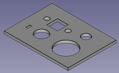 One more 3D
printing trick: I made a small test piece (left) for the
potentiometer shaft hole diameter and tab size/distance, as
well as the power-switch shaft diameter, square cutout for the SMA
jack, and
indicator LED hole. A lot less filament is wasted in reprinting a small
test piece than in reprinting an entire panel. The meter bezel
(translucent part in image at the top of page) is an artifact of this
same concept. I test-printed the meter hole and mounting screws
placement, then decided to use the test piece as a bezel. The minimum
depth of the enclosure is determined by the depth of the meter. Thus,
enclosure depth can be reduced by the thickness of the bezel, which is
another small advantage.
One more 3D
printing trick: I made a small test piece (left) for the
potentiometer shaft hole diameter and tab size/distance, as
well as the power-switch shaft diameter, square cutout for the SMA
jack, and
indicator LED hole. A lot less filament is wasted in reprinting a small
test piece than in reprinting an entire panel. The meter bezel
(translucent part in image at the top of page) is an artifact of this
same concept. I test-printed the meter hole and mounting screws
placement, then decided to use the test piece as a bezel. The minimum
depth of the enclosure is determined by the depth of the meter. Thus,
enclosure depth can be reduced by the thickness of the bezel, which is
another small advantage.
Miscellany:
The most expensive components of the present project are the AD8307 and
the
microammeter (if you don't have one).4
Early in the project I thought
that I had fried the AD8307 (DIP version) from Mouser,
and therefore I searched for a less expensive replacement. This led to
ordering a
3-pack of an SMD
IC from eBay ($5 for 3 ICs plus shipping). I replaced
the presumed dead AD8307 with one of the eBay chips (using an SMD to
through-hole adapter), and after doing so, found my error—it was
elsewhere! The
replacement
was not
needed, but it was good to know the AD8307 is
available in SMD form at much less
cost, and that the SMD is functionally equivalent to the DIP.
Demo video: RF_Field_Strength_Meter.mp4
1. White, W
(2021). A Sensitive Field Strength Meter for Foxhunting, QST 105(7), 34-35.
2. Ron Davis (K4TCP) private
communication.
3. The circuit was not exactly the
same, but equivalent from a practical or functional standpoint.
4. A length or loop of wire can be
used for the antenna if a small whip is not on-hand.
Project descriptions on this page are intended for entertainment only.
The author makes no claim as to the accuracy or completeness of the
information presented. In no event will the author be liable for any
damages, lost effort, inability to carry out a similar project, or to
reproduce a claimed result, or anything else relating to a decision to
use the information on this page.