Magic
Eye: The operative word for this project is ‘retro’—A
person would need to be about
a quarter century older than Pong
ever to have seen a magic
eye tube, or maybe even to know what one is.
If you don’t know what a magic eye tube is or what they were used for,
the web has many resources. This Wikipedia article is an
excellent summary. While this
page features great photos of different tube types and
display characteristics.
It is possible to purchase a magic eye
tube on eBay or from other sources. They are not expensive, but
require a high-voltage power-supply (as old vacuum tube radios and
stereo sets did). —Nowadays we are accustomed to sticking our fingers
into circuits without Fear of Dying! In any event, the
present project is not about magic eye tubes, as such. Rather, it is
about simulating
a magic eye using components that have
no filaments or plates!
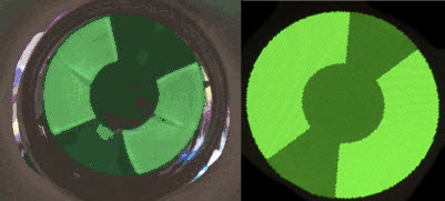 The image of a real magic eye tube (leftmost)
comes from the previously cited Wikipedia article, while the image next
to it is of a 1.5 inch OLED. An
RGB OLED is a colorful device, as is nicely illustrated by Adafruit’s
demo. When
I first began to experiment with this OLED, I felt some
regret about wasting all the colors except green. In a funny sense,
if RGB
costs $20.00 and the application only needs ‘G’,
then we’re wasting $13.33.
The image of a real magic eye tube (leftmost)
comes from the previously cited Wikipedia article, while the image next
to it is of a 1.5 inch OLED. An
RGB OLED is a colorful device, as is nicely illustrated by Adafruit’s
demo. When
I first began to experiment with this OLED, I felt some
regret about wasting all the colors except green. In a funny sense,
if RGB
costs $20.00 and the application only needs ‘G’,
then we’re wasting $13.33.
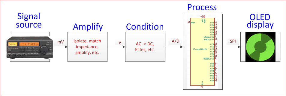
Inevitably, even
hair-brained ideas lead
to learning new things. The magic eye simulation project
introduced me to basics of
OLED screen geometry, pixel addressing, interfacing the display
via SPI, storing data in the microcontroller’s
program memory when an array of constants is too large to fit in
its dynamic memory, adapting a signal source,
and more.
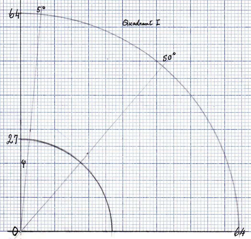 Classifying
Pixels: A 1-inch monochrome OLED has 128 pixels
across ×
64 pixels up-down; a 1-inch color has 96 × 64 pixels, while a 1.5-inch
color has 128 ×
128 pixels. Clearly the simulated magic eye image’s
resolution can be no greater than the number of pixels, so it suffices
to compute discrete image parameters within the bounds of the number of
pixels available. The
graph (left) represents one quadrant of a 1.5 inch color OLED display
(the
upper right). Each tiny
cell or corresponding coordinate point is one pixel. The outer circle
has the maximum radius that
can fit on the screen and the
inner circle is at 27 pixels from the center.
To arrive at this number I measured
the inner and outer diameters of
a magic eye
tube annulus, by placing a millimeter ruler on a corresponding screen
image. Then I applied the
same ratio to the OLED dimensions.
Classifying
Pixels: A 1-inch monochrome OLED has 128 pixels
across ×
64 pixels up-down; a 1-inch color has 96 × 64 pixels, while a 1.5-inch
color has 128 ×
128 pixels. Clearly the simulated magic eye image’s
resolution can be no greater than the number of pixels, so it suffices
to compute discrete image parameters within the bounds of the number of
pixels available. The
graph (left) represents one quadrant of a 1.5 inch color OLED display
(the
upper right). Each tiny
cell or corresponding coordinate point is one pixel. The outer circle
has the maximum radius that
can fit on the screen and the
inner circle is at 27 pixels from the center.
To arrive at this number I measured
the inner and outer diameters of
a magic eye
tube annulus, by placing a millimeter ruler on a corresponding screen
image. Then I applied the
same ratio to the OLED dimensions.
Pixels have integer coordinates. —Before
I began to
plan or code microcontroller functions it seemed probable that, for
satisfactory speed, all real time computations would need to
involve only integers. The control program should avoid decimal numbers
(floating
point) and of course trigonometric calculations etc. This
supposition led
to a strategy in
which essential data would be computed in advance, and stored for use
by
the wedge-angle adjusting function.
Warning: The next
two paragraphs mention math!
Through trial and error I arrived at a
visually acceptable maximum wedge opening of 100 degrees (50 degrees
per quadrant). The
task then became to classify pixels according to the smallest wedge
opening containing them, where openings are in whole degrees, 1
degree, 2 degrees, 3 degrees, etc. up to 50 degrees. In this context
‘opening’
refers to the
angle (labeled φ in the
graph) between the
vertical axis (centerline) and the wedge’s right-hand edge. Pixels that
lie
almost on an integer-degree
radius line (ray), but just outside it, should clearly
be included in that
measure’s classification.
Thus, in practice
boundaries are taken as the midpoints between pixels that lie adjacent
to the integer
degree radius lines.
At this stage another simplification
becomes obvious. For given x, and y1
< y2 , if (x, y1)
and (x, y2)
are classified in the same wedge (same φ),
then all (x, y), where y1 < y < y2 must also belong
to that wedge.
Thus it is not necessary to store all (x, y)
for each degree of angle, only at most two points for each φ ×
x. To
summarize, for each angle, we record a small set of four-tuples, (φ,
x, ymin,
ymax),
where ymin and
ymax
could be the same or a different number for each φ ×
x
combination. This array of constants is not extremely large, but too
large for the microcontroller’s
dynamic storage allocation. (I will return to this point.) Finally, we
define a small index array to point into this larger array, a quick
lookup if you will, for each φ.
This array’s
dimension is approximately the number of degrees corresponding to the
maximum
wedge opening in one quadrant, therefore easily
accommodated in the
controller’s dynamic
allocation.
 Microcontrollers are not computers. My desktop computer’s clock speed
is roughly 200 times that of the ATmega328PU. Word size is 64 bits
compared to the microcontroller’s 8 bits. For anything I would do, the
desktop’s
memory is essentially unlimited. Not so for the Atmel chip:
Microcontrollers are not computers. My desktop computer’s clock speed
is roughly 200 times that of the ATmega328PU. Word size is 64 bits
compared to the microcontroller’s 8 bits. For anything I would do, the
desktop’s
memory is essentially unlimited. Not so for the Atmel chip:

The reason that the magic eye sketch consumes more
than half of program storage space is that the array of constants
described in the preceding paragraphs is stored there. This page of the Arduino Reference
text explains the construct in detail. Array V (as it is named) and the
related index array (VNDX) were computed and formatted on my desktop
computer. I will omit details of this part, except to say that the
programming language used was one that is either loved or hated by
programmers.
Testing:
Before attempting to connect the magic eye simulation to a radio or
stereo it was necessary to verify that the wedge would open and close
smoothly and quickly enough to track a signal. For this part I coded
the display to track a [pseudo]random angle in a continuous loop. To
relieve the boredom of this demonstration I added sound effects in the
form of a tone whose pitch varies inversely with the opening. In other
words, wide openings are low-pitched and narrow openings high pitched.
(This stage of testing is included in the demonstration video.)
Actually, sound effects were implemented in two ways. Some people are
bothered by modulating pitches that do not coincide with musical notes,
so a variant substitutes random notes in place of random
pitches.
I did one final test before connecting the radio, applying a
voltage to the same microcontroller pin that would receive the
conditioned radio signal (pin A0). The OLED magic eye closes or opens
in proportion to the voltage applied, as expected.
In truth, testing was more involved than
can be easily summarized here. My early guesses as to what sort of
wedge-painting geometry would produce a satisfactory display were
wrong. Some did not
work at all, and others were too slow. Some filled the wedge in wrong
directions—inside out, or in chunks. I also had to learn how to update
the OLED efficiently. As luck would have it, the relationship between
pixel classification (as described above) and vertical line
segments turned my attention to the drawFastVLine(...) method of the
Adafruit GFX library. This drawing method seemed a perfect fit for the
chosen classification scheme. A faster algorithm may be possible, but
this is
the one that enabled the project to move forward.
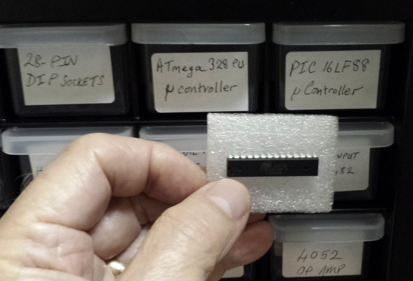
Signal
Source:
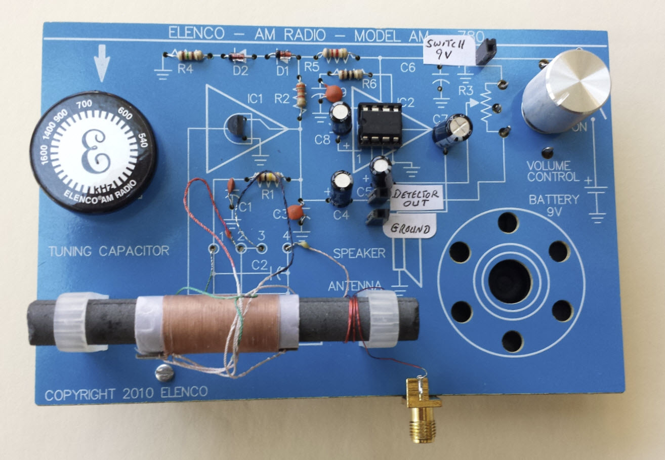
My wife suggested using an Elenco AM Radio Kit that she had assembled a
couple of years ago. Because the magic eye should not respond
differently at different volume levels, I tapped the detector output
(input to the audio stage), and amplified it off-board. The photo above
shows three connection points between the radio and the rest. I decided
to power the external amplifier from the radio battery, and have it
switch on/off with the radio. That is the ‘switch 9v’ tap at the top
right. The external amplifier is almost the same as the one in the
radio, the standard LM386 op amp circuit that you see everywhere. At
the output of the op amp, in place of a speaker is a rectifier circuit,
with some filtering. Thus signals (or noise) detected by the radio are
converted to a DC voltage level that depends on signal strength and
amplification factor. With this setup a 0.5 to 3.5 volts range can be
obtained,
suitable to
drive an analog input pin of the ATmega328PU.
The Elenco is sensitive to interference,
for example, from a nearby computer monitor, and relatively insensitive
to AM radio stations! However, this doesn’t much matter. Insofar as the
project is concerned, any signal will do to modulate the magic eye. AM
radio used to be a pleasant place, ballgames,
comedy, drama, music,
etc. But that was when
kilohertz were kilocycles. Between then and now daytime AM radio seems
to have been commandeered by conspiracy theorists,
political pundits, and religious interests.
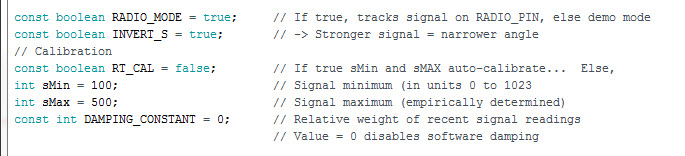
Calibration:
As has been explained,
depending
on how the signal source is interfaced electrically, different voltage
levels would be available at the microcontroller’s analog input. It is
important to keep the range between 0 and 5 volts DC for the
ATmega328PU or similar chips. However, the range can be considerably
less, while still sufficing to modulate the wedge angle smoothly. Near
the top of the control program (sketch) is a group of constants and two
variables that relate to interfacing with the signal source. The
constant RT_CAL enables or disables auto-calibration. This function
does not work well, because a brief out-of-range signal spike
pushes sMax to its limiting value (1023), which has the effect of
narrowing the range of the magic eye’s response to normal signals.
Manually adjusting the variables sMin and sMax through a
trial-and-error process works better.
Demo: OLED_Magic_Eye.mp4
Two years
later: At
the time that I did the OLED simulation
project, I wanted also to play with a real magic eye tube. With this
goal in mind I had bought a ‘kit’ consisting of a tube and socket,
together with other
parts needed to bias the tube properly as well as to condition a signal
to
modulate the grid. However, I had no way to supply high voltage to the
tube so I stuck the unopened kit in a drawer. I
was thinking high voltage = transformer, and transformers of the type
required are $40 or $50. Plus, a high-voltage electrolytic capacitor
would be needed to smooth the DC after rectifying, costing another few
dollars.
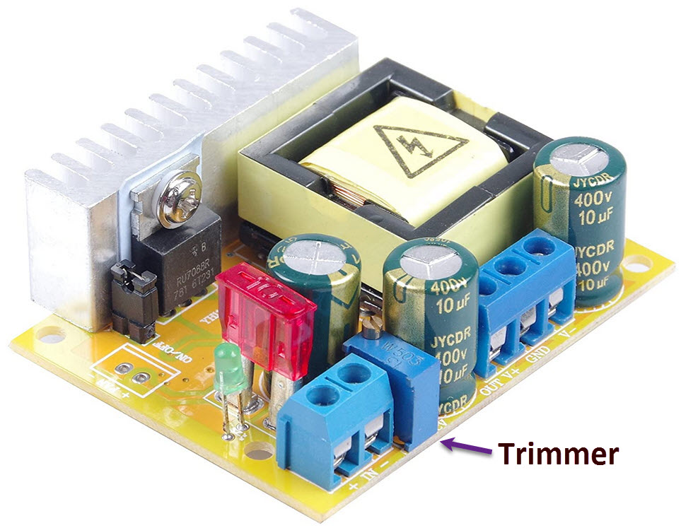 Recently, I ran across a DC-DC circuit that takes 10 to 32 volts DC as
input and puts out up to 700 VDC at a low current drain. There are
many different offerings for this circuit (Chinese)—I bought this one from Amazon for $11.99.
At first, I thought the power supply’s output voltage was supposed to
track input voltage, but just before I returned the ‘defective’ unit,
my wife found some helpful information on-line. Output voltage remains
constant across the range of input voltages but can be varied by
adjusting an on-board multi-turn trimmer potentiometer (invisible if
you don’t think to look for it).
Recently, I ran across a DC-DC circuit that takes 10 to 32 volts DC as
input and puts out up to 700 VDC at a low current drain. There are
many different offerings for this circuit (Chinese)—I bought this one from Amazon for $11.99.
At first, I thought the power supply’s output voltage was supposed to
track input voltage, but just before I returned the ‘defective’ unit,
my wife found some helpful information on-line. Output voltage remains
constant across the range of input voltages but can be varied by
adjusting an on-board multi-turn trimmer potentiometer (invisible if
you don’t think to look for it).
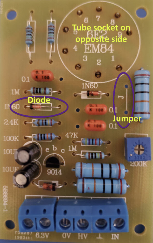
Once high voltage was available, I pulled the kit from the drawer and put it together.
The kit came with no printed instructions and I had to figure out a
couple of things. First, the polarity of one of the diodes was not
marked on the PCB but, on studying the circuit, that ambiguity was
easily resolved. Second, two holes and a line on the board were marked
‘j’. I immediately thought ‘jumper’ but wasn't sure. Again, by tracing
the circuit it became obvious that without a jumper at ‘j’ there would
be no voltage to pins 2, 6, 8 of the tube. It isn’t clear why the
jumper is not a trace—maybe some applications would have a switch
there.
Demo: EM84.mp4
Project descriptions on this page are intended
for entertainment only.
The author makes no claim as to the accuracy or completeness of the
information presented. In no event will the author be liable for any
damages, lost effort, inability to carry out a similar project, or
to reproduce a claimed result, or anything else relating to a decision
to
use the information on this page.