Reinventing the mail chime:
I honestly thought this was a novel idea until the project was about
90% complete. That is when a Google search found more than a few
attractively packaged consumer products that do the same thing,
probably better, and definitely cheaper. But where’s the fun in buying
something if you can make it yourself for twice the cost, and there’s a
outside chance it will work.
Alex (DD5ZZ) sent us a pair of RF24
development kits that he had designed—He calls them ZZduinos. Each
integrated kit includes two MPU’s: ATmega328PU and ATtiny, an RF24
module, a small OLED, power and I/O headers, and multiple test buttons
and switches for prototyping applications. After assembling the kits we
ran a test sketch to demonstrate 2.4 GHz communication between them,
and walked one of the units about a block from the house before losing
contact. Their potential was obvious, but for what? We knocked
around
one or
two ideas, and
then set the units aside.
 An idea that recurred from time to time was mail delivery notification.
Our mail delivery time is highly variable, from late morning to late
afternoon. Obviously it is desirable to retrieve QSLs from the mailbox
as quickly as possible, so that they don’t
rot. Thus it happened that one Saturday we went shopping for a mailbox
to
play with. The idea was to put the mailbox in one room with a
transmitter, and have the receiver in another room. In that way we
could
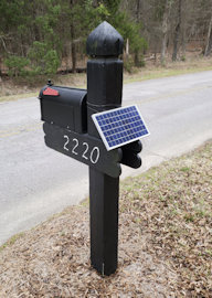
try out whatever was needed to make the scheme work. We purchased the
least expensive mailbox we could find (pictured), at $19.95 from
Home Depot. Our previous mailbox was metal. This one is plastic, but
that is good because plastic is essentially transparent to the
radio signal.
An idea that recurred from time to time was mail delivery notification.
Our mail delivery time is highly variable, from late morning to late
afternoon. Obviously it is desirable to retrieve QSLs from the mailbox
as quickly as possible, so that they don’t
rot. Thus it happened that one Saturday we went shopping for a mailbox
to
play with. The idea was to put the mailbox in one room with a
transmitter, and have the receiver in another room. In that way we
could
try out whatever was needed to make the scheme work. We purchased the
least expensive mailbox we could find (pictured), at $19.95 from
Home Depot. Our previous mailbox was metal. This one is plastic, but
that is good because plastic is essentially transparent to the
radio signal.
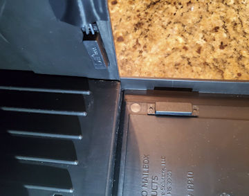 We first thought of using a motion sensor to
detect the mailbox door opening and closing—one of these was left over
from another project. This worked well enough for detecting changes
in the mailbox door’s state, but we wanted the circuit to report the
door’s current state (open or closed) unambiguously, and for this a
magnetic switch worked better. Switch wires were routed to the ZZduino
along a groove in the top of the box and secured with Scotch 88
electrical tape.
We first thought of using a motion sensor to
detect the mailbox door opening and closing—one of these was left over
from another project. This worked well enough for detecting changes
in the mailbox door’s state, but we wanted the circuit to report the
door’s current state (open or closed) unambiguously, and for this a
magnetic switch worked better. Switch wires were routed to the ZZduino
along a groove in the top of the box and secured with Scotch 88
electrical tape.
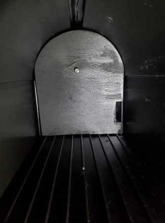 Electronic components were housed in a plastic project box and affixed
to the back bottom of a mailbox-shaped wooden cutout using Velcro. This
wooden piece was painted black, making a false back for the mailbox. To
pull it out easily we put a large screw in the middle—yes I know the
screw should also have been painted black.
Electronic components were housed in a plastic project box and affixed
to the back bottom of a mailbox-shaped wooden cutout using Velcro. This
wooden piece was painted black, making a false back for the mailbox. To
pull it out easily we put a large screw in the middle—yes I know the
screw should also have been painted black.
To reduce drain on the 4.2 volt battery
pack we removed the OLED and secondary MPU
on the mailbox end.
The ZZduino has selectable clock speeds, 4, 8, and 16 MHz. Normally it
would be set to run at the highest frequency, but again to conserve
battery a lower clock speed was selected. We made no provision
for
charging or monitoring the battery during initial field testing. Once
inside testing was complete, the mailbox was deployed to the street (on
a Friday). Nine days later we pulled the electronics to check the
battery level. It had dropped to 3.2 volts, an unacceptably low level.
Without provision for charging, it would be necessary to service the
battery pack weekly.
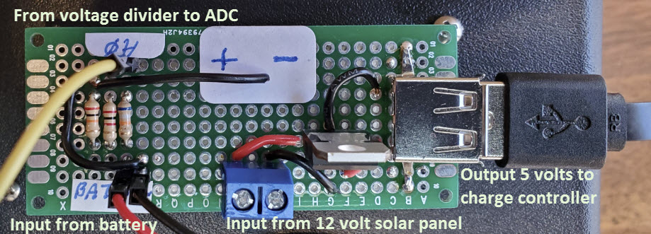
We had a small 12 volt solar panel
on hand
that had been used to charge a motorcycle battery that was in turn used
to power a QRP transceiver. Without calculating anything we decided to
try this solar panel with the mailbox battery. First an LM7805 dropped
the voltage to 5 volts. From there a TP4056 charge regulator connects
to the battery pack, supplying the 4.2 volt charge during
daylight
hours. We also added a battery voltage monitor feature at
the same time as the solar charger was deployed.
Whenever the mailbox was opened or closed it would report current
battery voltage.
 So far I have described only the mailbox end, the more challenging
part. The receiver inside the house does not need a solar panel as it
can be powered from a wall brick. However, to make things interesting I
decided to interface a real time clock. In that way we could see not
only that mail was delivered, but also the time of delivery.
So far I have described only the mailbox end, the more challenging
part. The receiver inside the house does not need a solar panel as it
can be powered from a wall brick. However, to make things interesting I
decided to interface a real time clock. In that way we could see not
only that mail was delivered, but also the time of delivery.
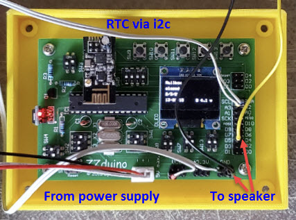
The Arduino tone() function was used to generate an audible
notification. A pair of brief ascending pitches indicated ‘open’ and
descending pitches indicated closure. This idea was cribbed from the
Four State QRP Group Hilltopper kit MPU code, where these two-tone
sequences are referred to as boobeep and beeboop. Electrically the tone
pin connects to the speaker through an electrolytic capacitor, without
filtering or amplification. Finally, timestamped notifications are
stored to EEPROM. There is no particular reason for this—just because
we can.
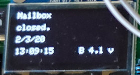
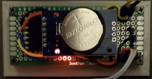
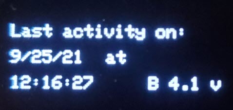
 The cell phone camera does not capture a sharp image of the small OLED
screen display. However, the zoomed image left is readable. The date
and 24-hour time of last delivery are shown on rows 3 and 4, and
battery voltage is reported at the lower right. This example reading
followed 5 days deployment, including two mostly sunny days. It appears
that the charging scheme will be adequate for southeastern US winters,
though no good for the Arctic circle or Germany.
The cell phone camera does not capture a sharp image of the small OLED
screen display. However, the zoomed image left is readable. The date
and 24-hour time of last delivery are shown on rows 3 and 4, and
battery voltage is reported at the lower right. This example reading
followed 5 days deployment, including two mostly sunny days. It appears
that the charging scheme will be adequate for southeastern US winters,
though no good for the Arctic circle or Germany.
The accompanying Arduino
sketch
includes code for both transmitter (mailbox) and receiver (house). The
first declared constant at the top of the program determines whether
the sketch behaves as transmitter or receiver. If MASTER = true it is
the receiver and if MASTER = false it is the transmitter. An
appropriate value must be set before loading the sketch to one
controller or the other.
Nineteen
months later:
(September 2021) The good news is that everything still works. The
small solar panel on the mailbox post keeps the transmitter battery
charged. Even after a few days of bad weather the 4.2 volt battery
still has enough juice to function. The bad news is that the small OLED
on the receiver (inside the house) became almost unreadable due to
pixel burnout. It was not a good idea to leave the display enabled 24 ×
7. However, small monochrome OLEDs are inexpensive, so a few days ago I
swapped the old one out. At the same
time I decided to revise the application so that the display would
timeout after a minute. With this change it would be necessary
to include a redisplay function to show the most recent
mailbox activity on demand, in case the original notification was
missed.
 While the mail
delivery notification sketch was being modified to accommodate display
timeout and redisplay functions, the application behaved erratically.
For example, on some tests it registered mailbox opening and closing,
but failed to display date and time, or battery status. After each such
anomalous display, the OLED failed to timeout, as if the main loop had
stopped running. These aberrant test results seemed to occur whenever
String variables were being manipulated or redisplayed. I
saw a joke on a forum somewhere that goes something like this: “To find
the cause of your Arduino error, search for ‘String’.” However, by way
of caution, it should be noted that the test platform was the custom
ZZduino board, not an Uno or other standard Arduino development kit.
While the mail
delivery notification sketch was being modified to accommodate display
timeout and redisplay functions, the application behaved erratically.
For example, on some tests it registered mailbox opening and closing,
but failed to display date and time, or battery status. After each such
anomalous display, the OLED failed to timeout, as if the main loop had
stopped running. These aberrant test results seemed to occur whenever
String variables were being manipulated or redisplayed. I
saw a joke on a forum somewhere that goes something like this: “To find
the cause of your Arduino error, search for ‘String’.” However, by way
of caution, it should be noted that the test platform was the custom
ZZduino board, not an Uno or other standard Arduino development kit.
Although
the true cause of the erratic behavior remained
unclear, I decided to switch to a much more powerful platform, namely a
Teensy 3.5. To get started, I salvaged a Teensy from a previously
completed project. After
making this hardware change the (putative) String-related problems
immediately disappeared and the revised sketch worked as designed.
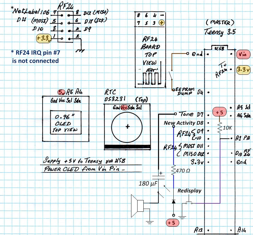
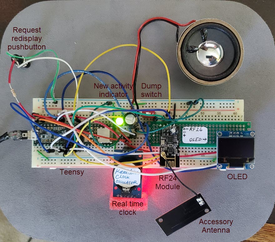
I did not draw a schematic for this
project, but made a worksheet to guide in connecting the correct Teensy
3.5 pins
to each accessory device (RF module, clock, and OLED). For the
illustration above
I have added annotations to show the additional parts (‘new activity’
LED and redisplay
pushbutton). I also added the speaker and EEPROM dump switch to the
worksheet for completeness. This more completely annotated worksheet
should serve the same use as a schematic diagram. —The photo below
shows
a tested breadboard implementation with all attachments.
Additional program code to support OLED
timeout and
redisplay-on-demand did not
appreciably increase complexity, as existing program code and variables
were reused when
possible. I am calling this version Rev.1T (T for Teensy)—download here. Maybe somebody will
have a go at porting it back to the ATmega328P. Although
the RF-24 module’s Serial Peripheral Interface (SPI) consumes five
digital I/O pins, and the indicator LED and redisplay pushbutton
consume two more pins, no Teensy-specific (high numbered) I/O pins
were
used. The code really
should work
the same on the Atmel MPU.
To be clear, the
revised sketch includes both transmitter (mailbox part) and
receiver (inside-the-house part), same as before.
Also as previously noted, a Boolean constant declared at the top
determines whether transmitter (MASTER = false) or receiver (MASTER =
true) will be functional at runtime. The transmitter (mailbox
part) was not changed in
this revision.
Project descriptions
on this page are intended for entertainment only.
The author makes no claim as to the accuracy or completeness of the
information presented. In no event will the author be liable for any
damages, lost effort, inability to carry out a similar project, or
to reproduce a claimed result, or anything else relating to a decision
to
use the information on this page.