Pi
exercise 2 - failure to
success: For
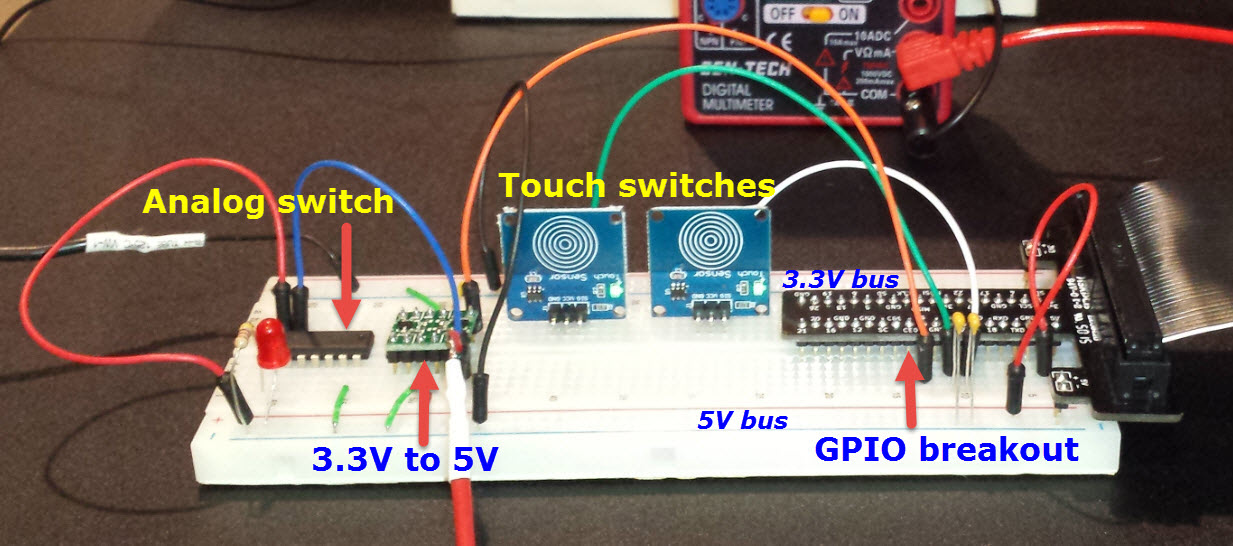
my second Pi exercise, which dealt with signal-level conversion
(hardware) and interrupt
processing (software), I
used a Pi 3 Model B. While Arduino digital I/O pins are 5V (TTL
level),
Raspberry Pi pins are 3.3V. In order to function as a TTL
input a GPIO 3.3V signal needs to be raised to 5V. For this I
used a TTL level shifter from MCM
Electronics. However, it would also be possible to make the
required voltage level change using only general purpose components.
The application itself was a
software
keyer. It was supposed to make either dots or dashes on touching one of
two capacitive sensors (see photo). In other words the program
would be an “event driven” application. Sometimes when I touched one of
the sensors a stream of dots or dashes would be produced, but other
times nothing happened. Once in a while, either a dot or a dash would
stick in the on
state. My first thought was that input pins were not
reliably firing or that corresponding interrupts were not being caught
reliably. Both these guesses were wrong.
In the back of my mind the program’s
structure was suspect, as
the event
handlers invoked
code to produce dots and dashes directly. As a final try I reorganized
the program so that event
handlers only set or reset global flags indicating to start or stop a
dot or
dash stream and nothing else. The part of the revised program
that
produces dots, dashes, and characters (the main part) executes a
continuous loop.
Moreover, the revised
program runs ‘nice’-ly,
relinquishing time when idle.
Transfer
to PCB:
Adafruit has a half-size prototyping PCB kit
that comes with a socket. I figured it would be just barely possible to
fit the Python keyer’s GPIO interface components on the small proto
board and although I will never use this keyer I wanted to do this—well,
I already had a
26 pin cable that mates with the proto board socket, and thought I
could plug the other end into the Pi’s
40-pin socket by sanding a little bit off the plug end. This much
worked, but I hadn’t
noticed that the ends of the ribbon cable plug are what hold it
together!
When the sanded end came apart I pushed the top of the plug back on and
rechecked
the continuity of each pin with an ohmmeter. Then I Epoxed the housing
and made a mental note not to pull on the cable while disconnecting the
plug—of course, one
should not do this even with an unmodified plug, but ...
There was no room for the touch sensors on the half-size board and, in
any case, they were not relevant to the ideas being tested. In
place of on-board sensors the small PCB has headers for attaching
either a paddle or other accessory.
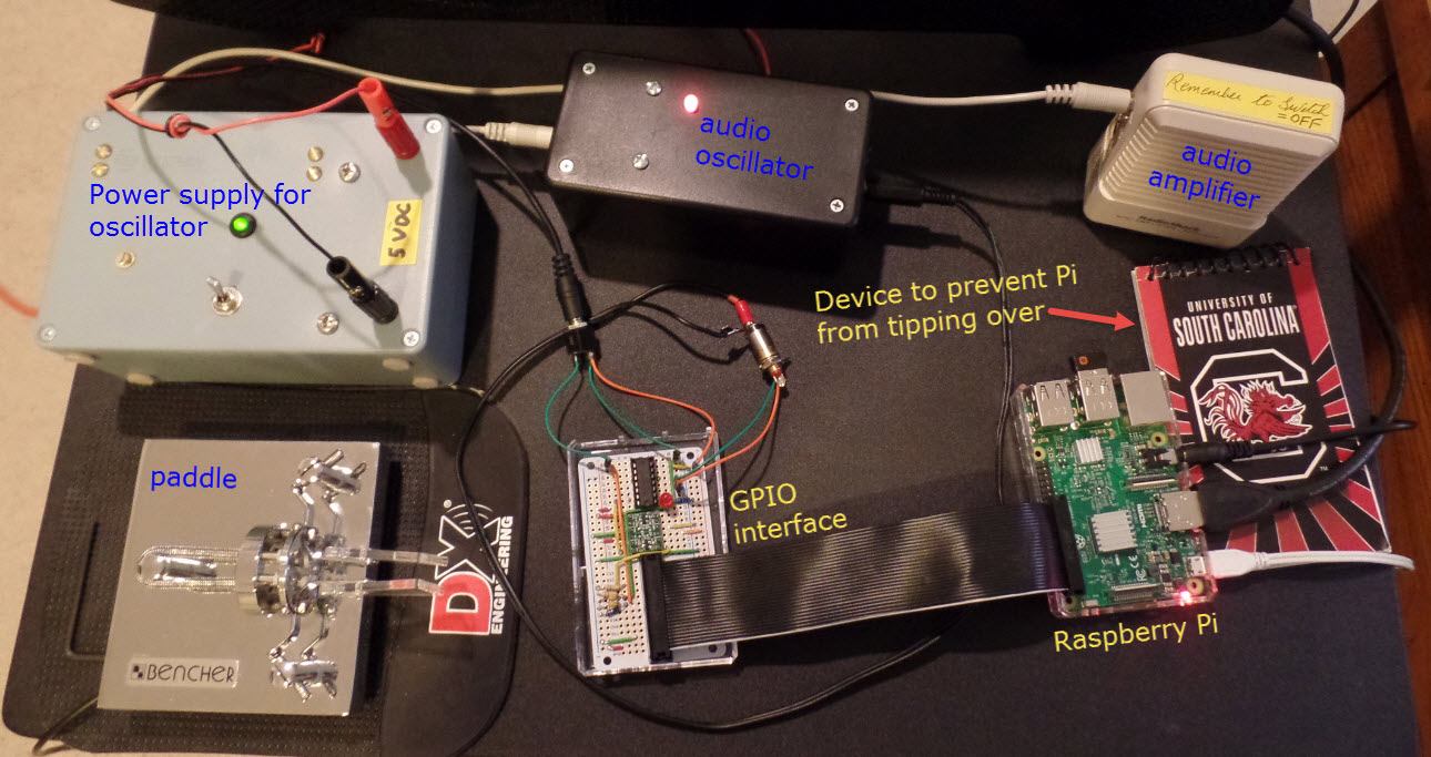
The test rig
for the Pi software keyer involves so many interconnected pieces as to
call
into question the sanity of whoever thought it up:
Demo: python-keyer-revised.mp4
Project descriptions on this page are intended for entertainment only.
The author makes no claim as to the accuracy or completeness of the
information presented. In no event will the author be liable for any
damages, lost effort, inability to carry out a similar project, or to
reproduce a claimed result, or anything else relating to a decision to
use the information on this page.