Hello world:
Arduino was a piece of cake! —That is, when compared to puzzling out
how to program a PIC microcontroller using Microchip’s
MPLAB X IDE
(version 4.05) and the PICkit™ 3 programmer. Looking
back on it, the effort should not have been as challenging as it seemed
to be at the time, but things that become
obvious in retrospect can be difficult to grasp when the language is
unfamiliar, or when one lacks confidence. Among the things
I did not understand at first were: 1) How to power the microcontroller
chip from USB
through the Programming interface, 2) How to refer to pins
on the chip using names that the compiler would understand, 3) How to
select or enable the chip’s
internal oscillator, 4) how to make timed delays, without a crystal and
finally, 5) how to disable the watchdog timer, or rather that such a
thing as a watchdog timer exists, much
less how to disable it.

 Routing USB power to the microcontroller by way of the Programmer
involves both
wiring and a software setting. The latter is shown
above. Google
searches did not return much useful information on the chip that
I was testing, except of course the datasheet. Later I came
to realize that the most relevant information was independent
of
the specific chip type.
Regardless of which microcontroller it is, Vpp goes to Vpp, Vdd to Vdd,
ground to Vss, data to data, clock to clock. Well, a point of confusion
was that microcontroller pins are multiplexed and serve multiple
functions, not
just application-defined input or output, but other functions as well.
For example, the COM data input pin on the PIC16LF88 chip is
labeled RB7/AN6/PGD/T1OSI and the clock pin says
RB6/AN5/PGC/T1OSO/T1CLI. For different chips, the number of pins or the
pin numbering scheme may vary, but common functions are similarly
named. The answers were
there—I just did not realize at first that they were answers.
Routing USB power to the microcontroller by way of the Programmer
involves both
wiring and a software setting. The latter is shown
above. Google
searches did not return much useful information on the chip that
I was testing, except of course the datasheet. Later I came
to realize that the most relevant information was independent
of
the specific chip type.
Regardless of which microcontroller it is, Vpp goes to Vpp, Vdd to Vdd,
ground to Vss, data to data, clock to clock. Well, a point of confusion
was that microcontroller pins are multiplexed and serve multiple
functions, not
just application-defined input or output, but other functions as well.
For example, the COM data input pin on the PIC16LF88 chip is
labeled RB7/AN6/PGD/T1OSI and the clock pin says
RB6/AN5/PGC/T1OSO/T1CLI. For different chips, the number of pins or the
pin numbering scheme may vary, but common functions are similarly
named. The answers were
there—I just did not realize at first that they were answers.
With an aim toward clarity, I tried a
couple of
different ways of illustrating connections from the programmer to the
chip. The Visio diagram (left) was about the best I could do. The Vpp
connection (orange line) is needed for programming, but not for running
(or when disconnected from USB and powered via Vdd). On the
microcontroller end, Vpp /
master clear is pulled high through a resistor when powered from the
target side. The
small capacitor from the MCLR pin to ground was recommended in a forum
thread. I am
not sure that it is needed.
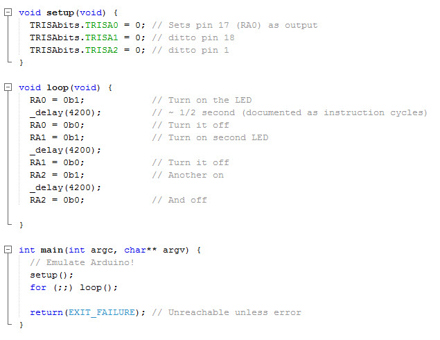
These are the basic connections and
setup required to program or run a program on the PIC16LF88,
and probably many other microcontrollers. An external oscillator or
crystal would involve a couple of additional pins. Similarly,
for demonstrating anything, such as blinking an LED, at least one
additional connection would be needed. I used RA0 for the first blink
demo, then added RA1, 2, 3, and 4 just for fun. I have not exercised
application input
yet.
My first programming test was intended
to make an LED blink once. Instead it blinked on and off continuously,
as if the thing had a mind of its own. This was extremely puzzling.
There was no way the program could be looping. Even so, I fiddled with
the program structure in crazy ways. The answer came from a Google
search on the terms pickit3
restarts main() this
thread. The following directive fixed the issue once and for
all —

It’s funny how a little thing can gunk
up the works so severely. One can’t
be sure that the cause isn’t an
opaque programming error, or defective
wiring or a bad chip.
However, once the
watchdog timer was disabled, the test program began to behave in the
intended
way. The LED only blinked when instructed to. Humans were once again in
charge!
For this first PIC exercise I used the free version of the MPLAB X IDE
with the XC8 compiler. For no particular reason I
decided to make the ‘Hello world’ code imitate an Arduino
sketch, initializing IO pins in a function named setup() and running
the demo in
loop(). Timing was a little funky. (I plan to add a crystal later.) In
order to use the XC8 compiler’s
built-in delay functions an
oscillator frequency should be specified, according
to http://microchipdeveloper.com/faq:26.
However, the _delay() function, whose argument is a number of
instruction cycles, produces the same duration delay whether or not
_XTAL_FREQ has been defined in the way suggested
at the ‘Developer Help’
page. Clearly there is much to learn, and many more experiments to do.
The present exercise is no more than a sort of necessary first step.
PICkit 3 demo: Hello_world.mp4
Project descriptions on this page are intended for entertainment only.
The author makes no claim as to the accuracy or completeness of the
information presented. In no event will the author be liable for any
damages, lost effort, inability to carry out a similar project, or to
reproduce a claimed result, or anything else relating to a decision to
use the information on this page.