Icom CI-V to UDP
Frequency tracking: Many ham radio RF
power amplifiers incorporate microcontrollers or board-level computers,
and are able to track the frequency of the transmitter or transceiver
that supplies drive power. This
allows them to change bands
automatically, or
in some cases to adjust a
built-in tuner. The feature is particularly useful when the station is
being operated remotely. Amplifiers pull off this trick in a variety of
ways. Most can ascertain frequency by sensing RF. Some have a serial or
virtual serial interface (or both) and some can receive information
from the transceiver over the local area network or Internet, either
hardwired or Wi Fi.
Overflow: In our shack1
an Icom 7610 drives an RF2K-S amplifier, which has a built-in
auto-tuner
and a Raspberry Pi 4B. The IC-7610 sends frequency information to the
amplifier using Icom’s CI-V command format. The transceiver’s remote
jack connects via an FTDI adapter to a USB port on the RF Kit
amplifier. If frequency is changed too rapidly, and many
update messages are sent in a short time interval, the amplifier touch
screen may stop responding. This is a known issue that the
manufacturer is working to correct (and may have done so by the time
this page is posted). Meanwhile many users have found a workaround that
involves using one of the popular computer applications that interface
with the transceiver, such as DXLab
Commander or N1MM
Logger. These applications are capable of forwarding
frequency information to
the amplifier’s UDP listener in a way that avoids the lock up.
No computer: On learning about this
workaround I wondered whether it
would be possible to do the same thing using a simple adapter that
would bypass the computer and advanced application software. In
response to a query that
N4EFS posted to an RF Kit forum,
Martin, CT1IQI,
described a custom
Python interface that he had written, and very kindly shared his code,
which clarified both the Icom CI-V command structure and the XML format
that the amplifier expects to receive when configured for UDP in place
of CAT. I had already begun experimenting with an ESP8266 (an
inexpensive development platform, about $2 to $3 US),
sending made-up UDP packets to a test server, and the rest of the
interface seemed straightforward.
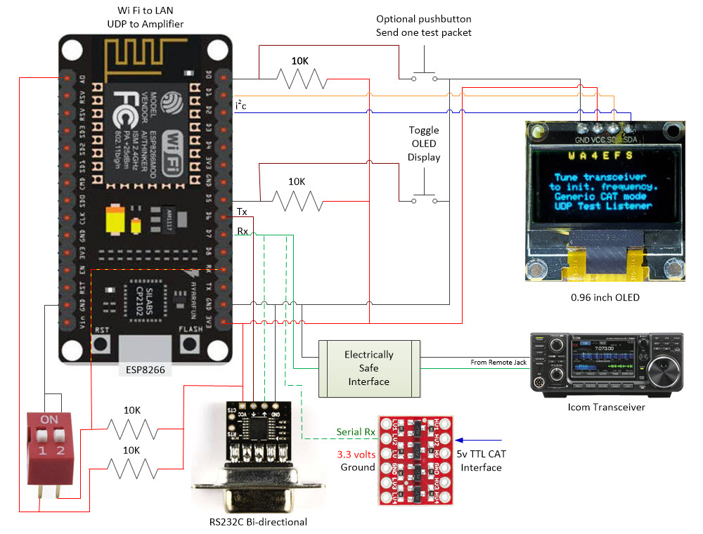
 Pacing, etc.: The project consists
mainly of software (firmware), which may be examined or downloaded here. The hardware part is simple.
The only component of the diagram at the top of this page that warrants
explanation is
the box labeled ‘Electrically Safe Interface’. That box is a
disclaimer. I am not responsible for how anyone except myself
connects the remote jack of an expensive Icom transceiver to anything
else. Before connecting to GPIO13 on the ESP8266 I measured the voltage
on the remote jack to be in the 3 volt range (3.0 to 3.3 on the
transceivers tested). Therefore I felt it was safe to connect CI-V to
this 3.3 volt input pin, which was allocated in the software for serial
Rx.
However, that was my decision for my transceiver. It does not
generalize to anybody else’s valued equipment.
Pacing, etc.: The project consists
mainly of software (firmware), which may be examined or downloaded here. The hardware part is simple.
The only component of the diagram at the top of this page that warrants
explanation is
the box labeled ‘Electrically Safe Interface’. That box is a
disclaimer. I am not responsible for how anyone except myself
connects the remote jack of an expensive Icom transceiver to anything
else. Before connecting to GPIO13 on the ESP8266 I measured the voltage
on the remote jack to be in the 3 volt range (3.0 to 3.3 on the
transceivers tested). Therefore I felt it was safe to connect CI-V to
this 3.3 volt input pin, which was allocated in the software for serial
Rx.
However, that was my decision for my transceiver. It does not
generalize to anybody else’s valued equipment.
Perhaps one other point deserves
explanation. The diagram shows two pushbuttons, while the photo shows
just one. The button that is implemented toggles the OLED screen
on-off, in order to prevent burnout. The other pushbutton in the
diagram was used to send a fixed-valued UDP packet, prior to
implementing the serial side of the interface. Once CI-V commands were
being received there was no further need for the test button.
Before sending packets to the amplifier
I exercised the interface with a handy UDP listener called UDP Client Server (Windows).
Netcat works the same for testing in Linux. The RF Kit amplifier
expects a frequency in tens of Hz, not Hz, so the number 706000 in the
example received packet below means 7,060,000 Hz or 7.06 MHz.

Although the amplifier wants 10’s of Hz for frequency values it is only
interested in
KHz—that is what it displays for frequency. At first I forwarded all
CI-V frequency updates, but when tuning the transceiver rapidly, the
UDP updates fell far behind, and most were pointless, since the
amplifier display changed only when KHz changed. So I made the style of
updating optional, and included a choice to send only KHz changes.
It is also possible to test with the
Arduino IDE serial monitor, if the ESP8266 is connected to a
computer (via USB). In that way, CI-V packets can be seen alongside the
amplifier screen. Of course, CI-V commands received by the ESP8266
and displayed by the serial monitor should reflect the actual
frequencies being tuned.

Icom CI-V addresses are
user-programmable. By default they are 0x88, 0x94, and 0x98 for the
IC-7100, IC-7300, and IC-7610, respectively, the three transceivers
that I tested. The latter two cover 160 through 6 meters, which is the
same coverage as the RF Kit amplifier. However, the IC-7100 also
includes 2
meter and 70 centimeter bands. Therefore I added the 100 MHz digit to
frequency parsing, although I do not anticipate having a use for this
generalization.
Loose Ends:
Near the top of the ESP8266 program (Arduino sketch) are a few
conditional compile directives (#define’s).
If implementing this sketch, comment-out any of these that do not
apply. Immediately below these directives is an ‘Interface Parameters
Section’. It is necessary to edit declarations and definitions in this
section, supplying Wi Fi connect credentials, the amplifier and/or test
server IP address, type of transceiver being used, etc. Near the bottom
of this section are three Booleans that control the pace of UDP
updating. These are preset to values that have worked for me, but can
be changed for experimentation.
Generalizations: Generic CAT,
RS232c, TTL
Non-Icom Transceivers: Icom
CI-V (the abbreviation stands for ‘Computer Interface 5’) is unusual as
ham radio transceiver interfaces go.
Electrically it is a bus, with transmit and receive on the same wire,
and  each
interfaced transceiver having a unique
assigned address. At the message
level, command labels and the command terminating character are
different than analogous CAT commands as implemented by Kenwood, Yaesu,
and others. It
happens that a Yaesu FT-991A sits next to my desk,
and
although I do not plan to use it with an RF amplifier, I was curious to
see whether its RS232c port could be connected to the
ESP8266 adapter to send the same XML-formatted frequency updates over
UDP as had been demonstrated for the Icom transceivers. There are
multiple convenient ways of interfacing transceivers and amplifiers—the
Yaesu CAT-to-UDP interface was an artificial
challenge.
each
interfaced transceiver having a unique
assigned address. At the message
level, command labels and the command terminating character are
different than analogous CAT commands as implemented by Kenwood, Yaesu,
and others. It
happens that a Yaesu FT-991A sits next to my desk,
and
although I do not plan to use it with an RF amplifier, I was curious to
see whether its RS232c port could be connected to the
ESP8266 adapter to send the same XML-formatted frequency updates over
UDP as had been demonstrated for the Icom transceivers. There are
multiple convenient ways of interfacing transceivers and amplifiers—the
Yaesu CAT-to-UDP interface was an artificial
challenge.
The first essential part of the solution
is an
adapter to convert RS232C to TTL. I found this one on Amazon, and noted that
it could convert RS232c to 5 volt or 3.3 volt TTL, according to
whatever voltage is supplied to its Vcc pin. That seemed perfect as the
NodeMCU is a 3.3 volt device. Since the message format and content are
also different, the sketch had to be extended to handle generic CAT
frequency messages. Finally, I did not realize until the start of
testing that it was necessary to poll the Yaesu transceiver with
frequency requests. It may be possible to have the transceiver send
updates automatically without polling—I don’t know.
Software (firmware) changes are
incorporated into an extended sketch, renamed as SER2UDP to reflect
that serial source data are not limited to CI-V format. The sketch may
be examined or downloaded here.
Hardware Enhancements:
Testing various combinations of transceiver, listener, message format,
updating frequency, etc. became a chore. Therefore, I added a
couple of
DIP switches. One of them selects between CI-V and CAT and the other
selects either the production (RF amplifier) UDP address or the test
listener address. If implementing this feature it is important to note
that GPIO3 (pin that handles the listener DIP switch) must either float
or be pulled high for flashing NodeMCU. If this pin is grounded (DIP
switch on), flashing will fail. After flashing, DIP switch 2 may be set
ON and the MCU reset to specify the test listener.
One last
hardware change was to add a level converter for interfacing a 5 volt
TTL signal. This addition was motivated by the desire to test with the Four
State QRP 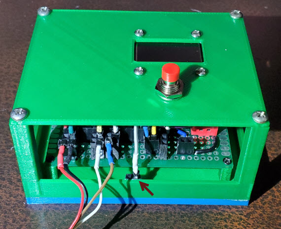 Group
Hilltopper (kit) transceiver.
To be clear I have no intention of interfacing the 5-watt Hilltopper
with a
big linear amplifier, but again,wanted to demonstrate to myself that it
could be done
in such a way as to communicate XML-formatted frequency updates over
UDP.2 Other
rigs may also use 5 volt TTL for CAT, in which case the level converter
would be a useful add-on.
Finally, to avoid have unconnected wires dangling about, I glued a pair
of female pin headers to the inside of the enclosure (photo left). If a
connecting
wire is not being used in the operative configuration, its terminating
pin
can be tucked into a dummy receptacle.
Group
Hilltopper (kit) transceiver.
To be clear I have no intention of interfacing the 5-watt Hilltopper
with a
big linear amplifier, but again,wanted to demonstrate to myself that it
could be done
in such a way as to communicate XML-formatted frequency updates over
UDP.2 Other
rigs may also use 5 volt TTL for CAT, in which case the level converter
would be a useful add-on.
Finally, to avoid have unconnected wires dangling about, I glued a pair
of female pin headers to the inside of the enclosure (photo left). If a
connecting
wire is not being used in the operative configuration, its terminating
pin
can be tucked into a dummy receptacle.
Generalizations: USB/FTDI → 3-volt TTL
→ CI-V
Computer to CI-V Remote:
The CI-V to UDP project described in the preceding paragraphs led to a
somewhat different application idea. Devices such as an RF
amplifier commonly interface directly with an Icom transceiver
utilizing CI-V, which is generally accessed via a 3.5 mm jack labeled
‘CI-V Remote’ on the transceiver’s rear panel. Computer applications,
on the other hand, normally connect via USB and communicate over
virtual serial channels. This addendum describes a hybrid configuration
in which a computer application (e.g., APRS, WSJT-X, Winlink) shares
the 3 volt CI-V bus with other devices. Transceiver soft settings are
the same for all. The setup is similar to that for the CI-V to UDP
interface, but simpler, as it does not involve connecting with a
network.
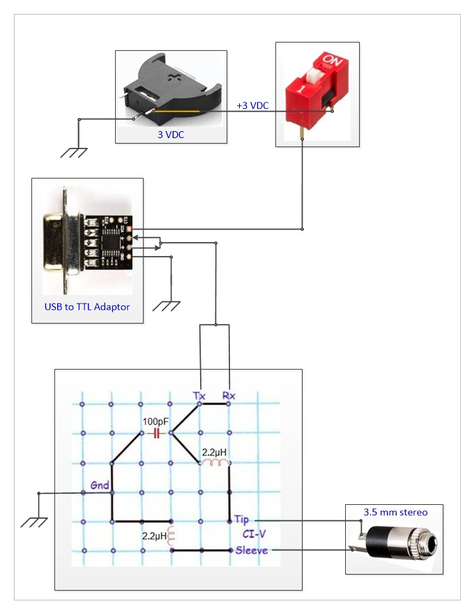
 The pictorial diagram above is similar to the main diagram at the top
of this page, but there is no microcontroller, no firmware, no WiFi. An
assembled version of the circuit is shown on the left. A USB/FTDI cable
from the computer plugs into an RS232 to TTL adapter that is powered by
the 3-volt coin cell battery in the foreground. (An LED power-on
indicator was added for convenience. The LED series resistor is 3.3K
ohms, so current draw is negligible.) At the other end, a 3.5 mm stereo
jack connects with Icom CI-V. Only tip and sleeve are wired. The ring
terminal is not used. The single 100 pF capacitor in the pictorial
diagram is not visible in the photo, as its location was blocked from
camera view by the coin cell.
The pictorial diagram above is similar to the main diagram at the top
of this page, but there is no microcontroller, no firmware, no WiFi. An
assembled version of the circuit is shown on the left. A USB/FTDI cable
from the computer plugs into an RS232 to TTL adapter that is powered by
the 3-volt coin cell battery in the foreground. (An LED power-on
indicator was added for convenience. The LED series resistor is 3.3K
ohms, so current draw is negligible.) At the other end, a 3.5 mm stereo
jack connects with Icom CI-V. Only tip and sleeve are wired. The ring
terminal is not used. The single 100 pF capacitor in the pictorial
diagram is not visible in the photo, as its location was blocked from
camera view by the coin cell.
In my setup, one other device (satellite tracking)
connects to the CI-V bus. Therefore, I used a multi-port stereo
splitter between the radio’s
CI-V Remote jack and connected devices. According to Icom
documentation, CI-V accommodates up to four addressable accessories.
The adapter described in these paragraphs essentially defines a
computer application as one of these CI-V connected devices, sharing
the same soft settings as other equipment on the wire bus.
1.
More accurately speaking, in N4EFS’s shack. I myself seldom operate,
and when I do it is usually just to test something.
2. In a previous project I made a
custom CAT interface for the Hilltopper (https://www.lloydm.net/Demos/Hilltopper-20.html)
and tested it with Ham Radio Deluxe. The frequency
message format was based on the Kenwood TS-440S CAT specification,
which is different than the Yaesu FT-991 frequency message. The latter
accommodates the Yaesu’s VHF/UHF as well as HF range. Since the
Hilltopper experiment was a one-off and not likely to be of general
interest, that specific adaptation is omitted from the revised sketch.
The sketch can be easily modified to match variations in frequency
message structure or content (length) between rigs.
Project descriptions on this page are intended for entertainment only.
The author makes no claim as to the accuracy or completeness of the
information presented. In no event will the author be liable for any
damages, lost effort, inability to carry out a similar project, or to
reproduce a claimed result, or anything else relating to a decision to
use the information on this page.
