Coax Continuity Tester: The
object of this
project was to play around with
logic circuits (TTL) along with computer software for logic circuit
design and
analysis. It is trivial to test the continuity of an ordinary length of
coax using an ohmmeter. Touching the ohmmeter probes to the center
conductor at
both ends should show near zero resistance, and the same for the
shield. Probing between the center conductor and shield
should
indicate an open circuit (infinite resistance).
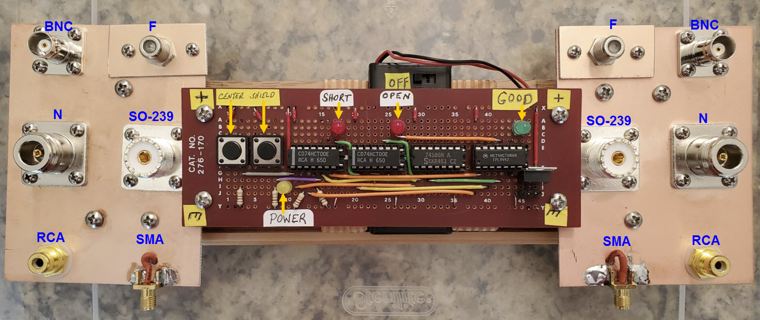
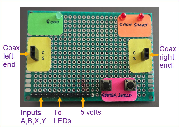
Flying Saucer Coax Tester
The tester pictured above has four TTL chips, two pushbuttons, three
LEDs, some visible point-to-point wiring, and additional wiring under
the circuit
board. When a cable
is
connected between two coax jacks, one from the
left copper panel and one from the right,
pressing the left pushbutton (near left end of circuit board) tests the
center
conductor. Pressing the other button tests the shield. The
green LED indicates that the tested conductor is good. The red ‘Open’
LED indicates a break in continuity, while the other red ‘Short’ LED
indicates a short circuit between center conductor and shield. Since
the unit is battery powered I thought
it would be prudent to include a power indicator as well (yellow
LED).
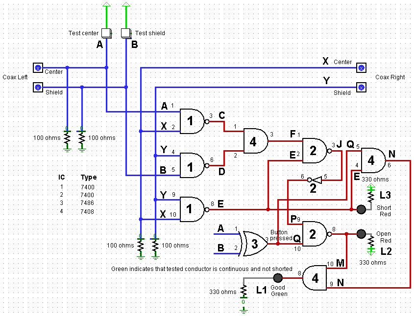
I first drew the planned circuit using
the
program Logisim.
After making a couple of
simplifying revisions I constructed the project on a
breadboard and it
appeared to work as intended. At this point I became curious
as to
whether I could write down a valid logical expression for the ‘Good’
indicator, based on the four inputs (center left, center right, shield
left, and shield right). However, I tended to make
mistakes, such as having unbalanced
parentheses or a missing or superfluous ‘not’ symbol. So
instead I wrote a simple computer procedure that accepts a list of
equations as input, each equation corresponding to a single logic gate,
and additionally a target expression—the thing to solve for.
By iteratively substituting symbols the procedure converts
the target expression to a form that references only input variables,
stopping
when no further simplification is possible.
Using this ‘helper’ utility I was able
to obtain an expression
for the ‘Good’ indicator.
Next, a Google search for ‘logic simplifier software’ yielded several
relevant resources. The one that I ended up using is another
excellent free program called
Logic
Friday. My goal
was to create three expressions, one for each indicator LED, then to
simplify each, and in the end to produce a simplified combined
circuit. However, when I entered the ‘Good’
expression into Logic Friday the program’s
truth table included two unexpected rows. After spending a lot of time
proofreading the circuit and double-checking the breadboard
implementation, a question popped to mind: Had I really tested the
exact
combination of inputs that unexpectedly evaluated as good? The
truth table was saying that if one of the coax conductors was open and
the other not, AND if both buttons were pressed simultaneously the
‘Good’
indicator would illuminate. Upon testing these exact conditions that
was
what indeed happened. This unanticipated observation led to a
minor change in the logic, after which the truth table exhibited by
Logic Friday consisted of only two rows, corresponding to a good center
conductor and good shield.
This
account has omitted details of the analysis, but supplementary
information
may
be found here. In any case, the
logic diagram shown below corresponds to the circuit that was finally
implemented (photo at
the top of this description). It is revision 4 of the
original
seat-of-the-pants
design. Note that the two fault LEDs are inverted, and
also that coax center and shield probe pins are not
connected in the diagram.
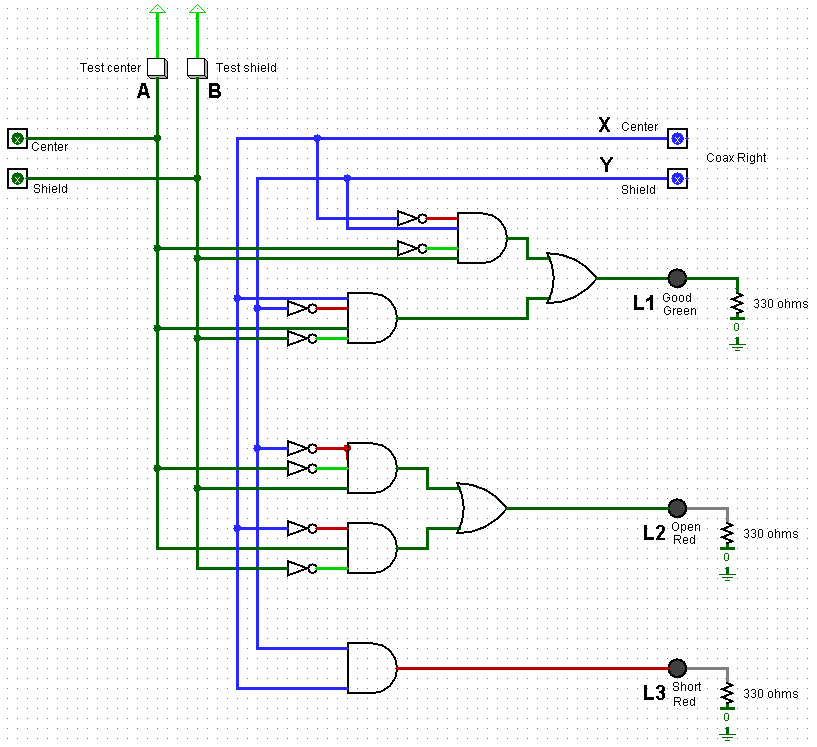
Logic Friday includes a ‘Minimize’
option that accepts a messy equation as input, and produces a minimized
version of the same logic. It is then possible to
translate the minimized expression back into a circuit. Combining
separate minimized circuits without
further simplification leads to the following diagram, which has not
been
implemented or tested. (However, see Arduino addendum below.)
Since the diagram above represents a
combination of three independently derived circuits, it includes some
redundant
elements (duplicate
inverters). In general,
minimizing logic in a small-scale circuit
such as this one is not necessarily the same as minimizing the circuit,
due in part to the way that gates are packaged in ICs. Other
considerations include the ready availablity of ICs or their cost, if
they must be purchased.
Coax continuity tester: TTL/coax_tester_demo.mp4
(Video shows early version of tester, before additional coax jacks were
added.)
* * *
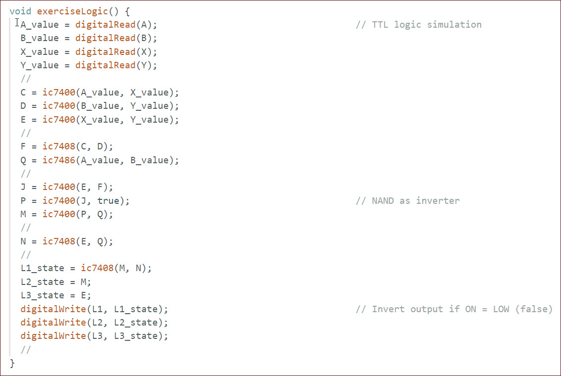
Arduino Logic Simulation
: (June
2025) - A functionally equivalent Arduino application is a natural
project idea, and one that would be easily implemented from
scratch. Perhaps a less obvious approach would be to duplicate the TTL
logic exactly as described in the preceding paragraphs, in other words
to construct a one-to-one mapping of the TTL circuit’s logic functions
to an
Arduino sketch. Every input and output in the diagram has a one or two
character label: LEDs are L1, L2, L3; the rest are single letters. The
previously referenced supplemental pdf
refers to these same labels when representing the circuit’s logic gates
as equations. In a similar vein, each gate can be represented in
computer programming language form as a boolean operation. For example,
the ic7408 AND gate may have the following implementation:

Each logic gate shown in the TTL coax continuity
tester circuit
diagram can be defined in a similar way, as a one-line boolean return
expression. The J-to-P inverter (NOT) is implemented as a NAND gate
with one of its inputs pulled high. This is indicated in the original
diagram by the inverter’s numeric label ‘2’, which references IC type
7400. When all integrated circuit logic functions have been thus
defined, the entire circuit can be expressed in programming language
form, starting at the top of the leftmost column of gates, and
proceeding from top to bottom, left to right through the diagram. This
one-to-one mapping procedure leads to the following Arduino code:
The Arduino sketch may be examined or downloaded
from here. The
choice of digital pins to use for inputs and outputs is more-or-less
arbitrary. I tested this implementation using a Sparkfun RedBoard, essentially an Arduino Uno
equivalent. The RedBoard may also be purchased from Amazon.
A simple test jig was used to exercise the Arduino sketch for all input
conditions that pertain to testing real coax, but substituting pin
headers in place of coax connectors.
The TTL circuit diagram specifies 100 ohm resistors to pull down center
and shield TTL inputs. In place of these resistors the test jig has
four voltage dividers to bias the corresponding Arduino inputs (labeled
A, B, X, Y). Each voltage divider consists of a 20k and 1k resistor in
series. Thus, when not driven high by a test button press, each digital
I/O input is pulled to 1/20 × 5 volts = ¼ volt = logic LOW (false).
IC Chip Simulation:
The preceding few
paragraphs describe an Arduino-based coax continuity tester, where
microcontroller code performs each logic function in the original
diagram: and, nand, etc. The simulation (mapping)
is one-to-one, physical TTL gate to virtual TTL gate, preserving ID
labels from the circuit diagram as variable names in the code.
There is another way in which the circuit could have been simulated.
Instead of mapping logic functions, map entire multi-pin integrated
circuits. To explore this approach I created a code library that
currently simulates 32 different kinds of TTL chips (download zip here). Only integrated
circuits having 16 or fewer pins are included at present. However, more
and larger devices are easily
appended.
To exercise this alternative simulation, the caller
instantiates a chip as Arduino type uint16_t,
and, after setting input pin values, passes the chip to the appropriate
library function by reference. The chip-specific
function performs all logic defined for the chip, and then
returns. At this point the caller examines the relevant output pins,
and continues the process with the next IC for which input values are
available, and so on. The code snippet below illustrates setting up the
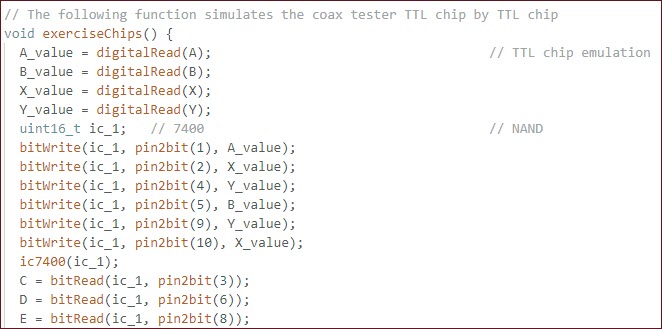
7400 quad 2-input nand IC #1 in the coax tester diagram, calling the
corresponding library function, and sensing/reading outputs.
Not surprisingly the result is the same when the
entire TTL coax continuity tester circuit is simulated in this way. All
test conditions (good, open center, open shield, short) are correctly
identified. This simulation success leads to another idea, namely to exercise the Logic
Friday minimized circuit in the same way. I do not have any 3- or
4-input physical AND gates on-hand, but virtual AND gates of any
desired input configuration are in infinite supply.
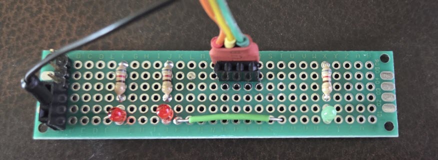
The Logic Friday solution enables outputs in a
consistent way. All LEDs are enabled high. To avoid fudging this part,
I made another small jig consisting of just the output LEDs (above).
The Arduino simulation matches Logic Friday’s diagram with one
exception. Being a composite of separate functions, the diagram
duplicates inverting the inputs (not A, not B, not X, not Y). It would
be pointless to duplicate these inverters in code. Therefore, just one
virtual 7404 (hex inverter) was used in the simulation.
All test conditions passed, the same as with the
original TTL circuit, and with the two previous simulations. Thus, the
Logic Friday minimization was proven valid. It
would have been possible, of course, to prove the circuit using Logism,
without either a test jig or Arduino code, but the Arduino exercise was
instructive and satisfying. The revised sketch with the additional
test code described in these addendum paragraphs may be examined or
downloaded here.
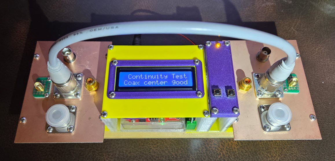
It would be simpler to make a practical coax
continuity tester using the Arduino platform than to construct the
discrete TTL chip circuit described at the beginning of this page. The
device could be made without buttons or LEDs. Each conductor could be
tested separately and automatically by the control program and,
optionally, a textual display substituted for
the result, “Continuity good” or “Center open”
or etc. The original TTL-based device has
served well. I have used it many times when preparing a new cable run,
or custom adapter. On the other hand, ...
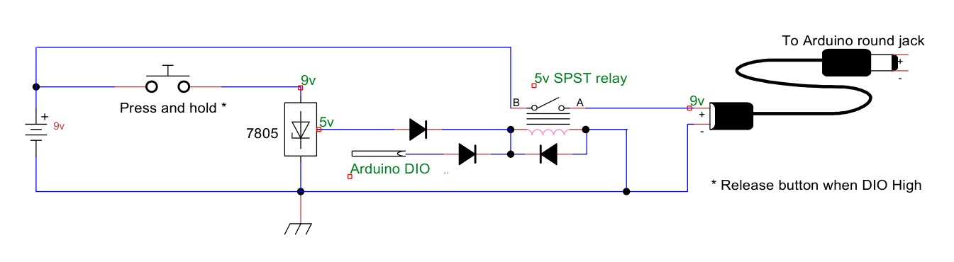
Final thoughts:
One of the challenges with battery-powered devices is remembering to
switch them off, or to power-save mode. A 9-volt battery connected to
the Red Board auxiliary jack (round)
suffices to power the Arduino and LCD with backlight, as well as
accessory LEDs, if included. Would it be feasible to power-off the
Arduino-based continuity tester automatically after a defined period of
inactivity? I don’t know if a circuit that has zero off-current draw is
possible, i.e., the same as a mechanical SPST
switch. However, if off-current were small enough, such a circuit would
likely have negligible effect on battery life. Something to think about!
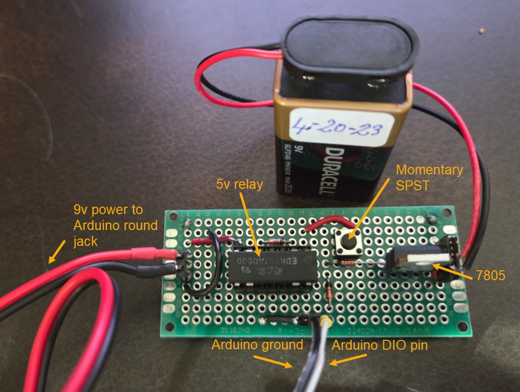
(Later) Not much thinking was needed. The simple
circuit shown above consumes no power when the Arduino is off, and
almost no additional power when it is on. One DIO pin powers the relay
coil. The diodes are the ubiquitous 1N4148 type (because I have at
least a hundred of them). The relay is type EDR201A0500, again because
that type was on hand. The relay should require minimum current to
operate.
Software was simpler than the hardware, if that is
possible. I set the inactivity-shutdown time to 1 minute for testing
(60,000 milliseconds in Arduino time). Time of last activity gets
updated each time a button is pressed. DIO pin
#8 was used to activate the relay, HIGH = on, LOW = off. Of course, any
pin that is not otherwise used will do. The relay pin goes high
immediately on startup. Thus it is only necessary to press the button
for a second. In testing I held it until the LCD came on and then
released it. By this point the Arduino is powering the relay coil via
the specified DIO pin. Once the inactivity-shutdown time interval
expires, the relay pin drops to LOW, interrupting power. Pressing the
momentary SPST button again restarts it.
Project descriptions on this page are intended for entertainment only.
The author makes no claim as to the accuracy or completeness of the
information presented. In no event will the author be liable for any
damages, lost effort, inability to carry out a similar project, or to
reproduce a claimed result, or anything else relating to a decision to
use the information on this page.