Oven Controlled Crystal
Oscillator
Precision Frequency Measurement: What would you
do if you were stuck in an underground bunker with no GPS
signal and your life depended on making a precise frequency
measurement? An improbable scenario, perhaps, but as the Boy Scout
motto
says, “Be
prepared!”
In previous project write-ups I
described a
GPS-disciplined frequency counter and,
subsequently, a rebuild
using surface mount components.
At the time of carrying out these projects, and writing about them, I
was
only dimly aware of something
called an ‘oven-controlled
crystal oscillator’ (OCXO). Some time later I read about OCXOs,
and their applications.1
To appreciate the potential usefulness of OCXOs, the
keyword
is stability. Once
fully
heated the OCXO shown in the photo above produced a nearly constant
output frequency, certainly less variable than would be expected from
an ordinary
crystal oscillator in a typical application environment.
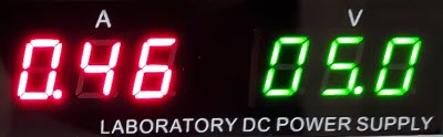
When first powered-on, the OSC5A2B02
draws about half an amp at 5 volts. As its temperature increases,
current
drain
gradually decreases, settling to about 200 mA. Although
I had thought when purchasing a couple of used (reclaimed) OCXOs
on eBay, that their frequency should be adjustable—within a limited
range—I did not immediately see how to do this. However, I realized
that from the standpoint of deriving a time interval for counting
a test signal, the exact OCXO frequency doesn’t matter, as long as it
does not change appreciably.
 Sometimes I do
not see the thing that is staring in my face. —In this case it was the
pin labeled Vref in the photo, and referred to
as
Vc on the OSC5A2B02 datasheet. Biasing this
pin with 2 volts ± 2 volts corresponds to a tuning range of -1 ppm to
+2 ppm (i.e., -10 to +20 Hz at 10 MHz). By the time I got around to
experimenting with the Vref pin I had invested a great deal of time in
other investigations, some of which were of potential use,
others dead-ends. (I will return to this point.) In any case,
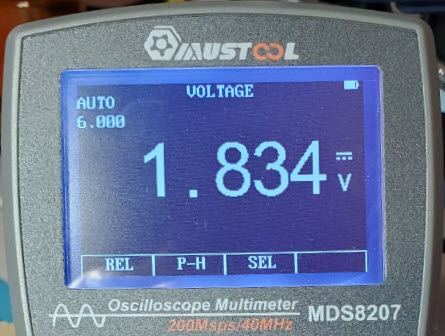
as
the photos accompanying this paragraph illustrate, by adjusting the
bias to approximately 1.8 volts it was possible to tune the
heated oscillator to a frequency of 10 MHz exactly. Furthermore, with
the OCXO
temperature stabilized at approximately 200 mA current draw, its output
frequency remained constant for a considerable time afterwards.
Sometimes I do
not see the thing that is staring in my face. —In this case it was the
pin labeled Vref in the photo, and referred to
as
Vc on the OSC5A2B02 datasheet. Biasing this
pin with 2 volts ± 2 volts corresponds to a tuning range of -1 ppm to
+2 ppm (i.e., -10 to +20 Hz at 10 MHz). By the time I got around to
experimenting with the Vref pin I had invested a great deal of time in
other investigations, some of which were of potential use,
others dead-ends. (I will return to this point.) In any case,
as
the photos accompanying this paragraph illustrate, by adjusting the
bias to approximately 1.8 volts it was possible to tune the
heated oscillator to a frequency of 10 MHz exactly. Furthermore, with
the OCXO
temperature stabilized at approximately 200 mA current draw, its output
frequency remained constant for a considerable time afterwards.
While
the GPS pulse-per-second (pps) is accurate to better than a
billionth of a second,
the temperature stability of the OCXO type that I purchased is claimed
≤ ± 10 parts per billion (ppb) and, from
direct
observation, as noted above, the OCXO frequency remains very nearly
constant (within 1/4 hertz) for a long
time after it has fully heated. To apply the OCXO’s frequency
stability to
counting or measuring a test frequency, an obvious approach would
be to derive a
timing interval from it, analogous to the GPS pulse per second.
Clearly,
a one-second pulse could be obtained by dividing the OCXO frequency
by ten million (107). The quotient would be
a time interval that is extremely close to 1 second, though not as
precise as the GPS. Thus, it would be possible to modify and extend the
GPS-disciplined frequency counter to use an OCXO time base if
needed.
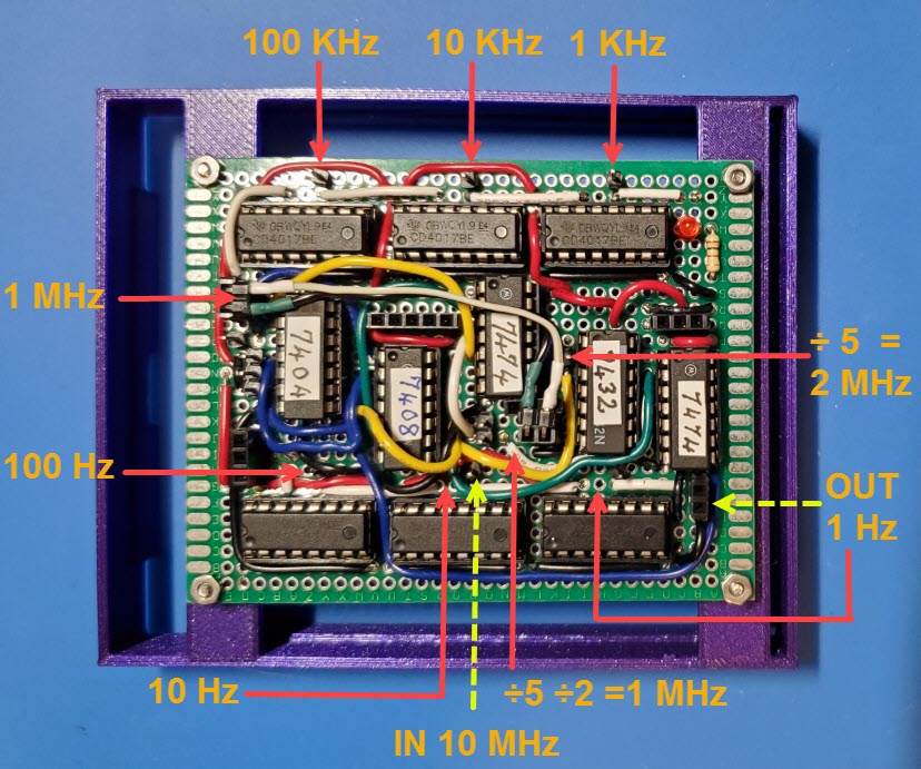
Dividing
the crystal frequency by 107
seemed straightforward,
but involved a small quirk. I had purchased type CD4017BE decade
counters with the idea of using seven of them to divide the frequency
from
10 MHz to 1 Hz. However, the specified maximum clock input
frequency for these ICs was 2.5
MHz at
Vdd = 5 volts. Through
testing I ascertained that the 4017s counted or divided correctly up to
an input
frequency greater than 10 MHz. Even so, it would surely be better to
adhere
to the published specification, which meant that faster devices should
be used for the first divide-by-10 stage. Therefore,
for the first stage of division (i.e., from 10 MHz
to 1 MHz) I experimented with a couple of counting circuits from the
Internet before running across what
seemed a superior solution in a paper titled Clock Dividers Made Easy, by Mohit
Arora of ST Microelectronics Ltd. At the top of page 12 is a
divide-by-5 circuit that uses three ‘D’ flip-flops, augmented by two
AND gates, one OR gate, and four NOTs (inverters). When constructed on
a breadboard, this circuit, adapted to match ICs that were on hand,
performed as
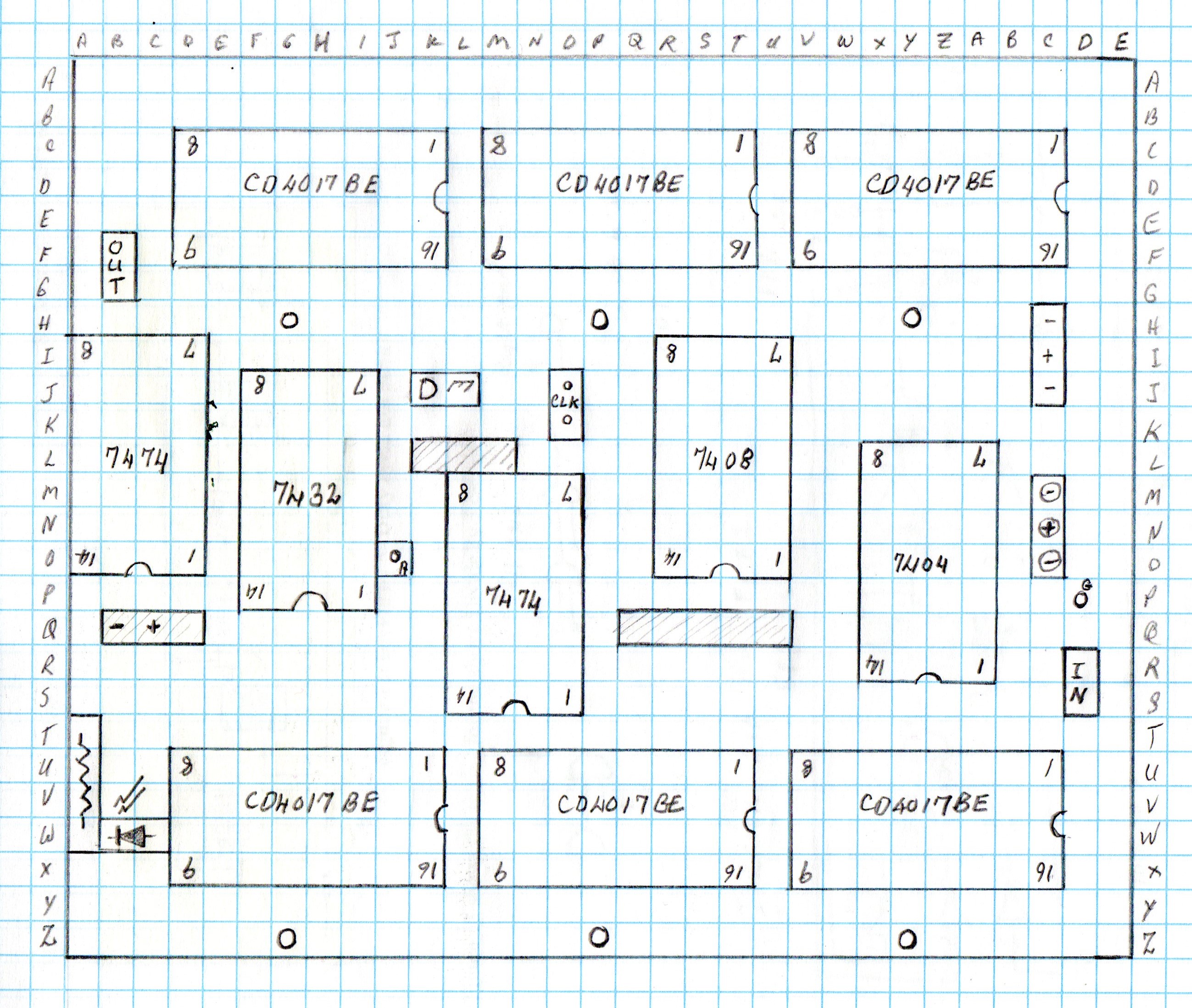
promised (my drawing below).

The divide-by-5 circuit
consumes three
D-flip flops, or one and one-half TTL
type 7474 ICs, leaving
one flip-flop
available for the divide-by-2 part (bottom of drawing). Before adding
this first stage I had already soldered six CD4017 IC sockets and three
female headers on a
prototype
circuit board, and had left no room for anything else, intending that
the first divide-by-10 stage would occupy a daughter board. But then I
decided to try to squeeze the five additional ICs onto the same board.
Somewhat to my surprise, they were able to fit, though just barely.2
To make room for the divider board, the frequency counter enclosure
also required a redesign. The revised enclosure consisted of three
levels and a top panel.
The bottom level housed the original
SMD
frequency counter board. The divider substrate (above) was the second
level. The
third level (annotated below) had the binary LEDs panel on the front.
The power jack, SMA jack (signal to be measured), a 4-pin
female DIN
connector (for the GPS or OCXO plug-in), as well as a small reset
button and
SPST toggle switch are on the back. For this version I did not bring
out
connections for the input signal pre-amplifier. If needed, an
external preamplifier could be used. In the photo below the top panel
has a rotary encoder in place of the original GPS frequency counter’s
normally closed pushbutton. I will explain what that is about shortly.

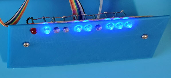 Practical constraints: The original
GPS-disciplined
frequency counter, with its decorative binary LED display (photo
right), consumed all
ATmega328P digital and
analog I/O
pins, except digital pins
0 and 1, which were reserved for the serial interface. The ‘Request
measurement’ pushbutton was a normally closed type, because
that
is what
happened to be handy when I constructed the prototype. I
puzzled over how the design could be extended to allow substituting a
rotary encoder in order to permit runtime
calibration
adjustment of an imprecise time base. If a rotary encoder were
to
be used, its integral pushbutton switch would be of the normally open
type.
And which
MPU pins
could be assigned to the clock and data signals? It
seemed there was no choice but to use MPU pins 0 and 1 for the latter.
In truth, there was the choice of eliminating the
decorative binary-remainder LEDs, but I like flashing LEDs.
Practical constraints: The original
GPS-disciplined
frequency counter, with its decorative binary LED display (photo
right), consumed all
ATmega328P digital and
analog I/O
pins, except digital pins
0 and 1, which were reserved for the serial interface. The ‘Request
measurement’ pushbutton was a normally closed type, because
that
is what
happened to be handy when I constructed the prototype. I
puzzled over how the design could be extended to allow substituting a
rotary encoder in order to permit runtime
calibration
adjustment of an imprecise time base. If a rotary encoder were
to
be used, its integral pushbutton switch would be of the normally open
type.
And which
MPU pins
could be assigned to the clock and data signals? It
seemed there was no choice but to use MPU pins 0 and 1 for the latter.
In truth, there was the choice of eliminating the
decorative binary-remainder LEDs, but I like flashing LEDs.
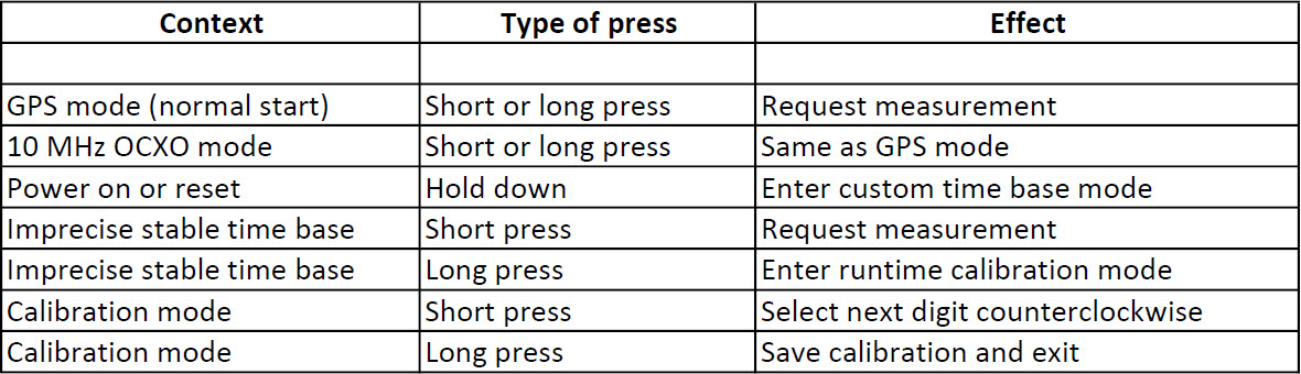
Solution: The
table below shows how a single pushbutton
was adapted to
perform multiple functions associated with incorporating a switchable
OCXO time base. The trick was to distinguish between a short and long
press. In order to accommodate
the normally-open rotary encoder button, I used a spare TTL inverter on
the
‘divider’ board, and
left the button sensing part of the
MPU
program unmodified.3
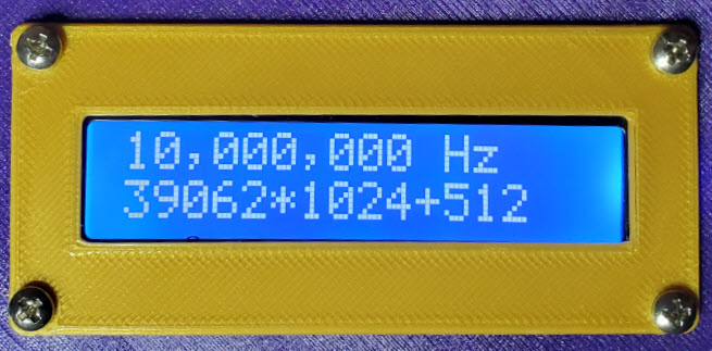
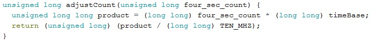
Software: As previously remarked, the justification for
relying on a stable
crystal oscillator at a known frequency near 10 MHz
is that the exact value
of the counting interval can be easily computed. It is the oscillator’s
actual frequency in Hz divided by 107.
This fact makes it possible to correct a test count and to obtain
a very
good
frequency measurement. Thus
the
microcontroller code was modified to accommodate editing a
custom (imprecise) time base ‘constant’,
and to store the correction in EEPROM. In GPS mode, there is
no
correction to the counted frequency, while in custom time base mode the
4-second
count gets adjusted for the oscillator’s true frequency. Implementing
this correction
was tricky, as 4-second count numbers are big, and Arduino
C++ does not like big numbers. Code
for correcting the raw count
(below) was a bit of a
guess, but it appears to work. The
complete revised sketch, including
OCXO
support, may be examined or downloaded here.
Kitchen
Clock: That is my nickname for a clock that is based
on a 32,768 Hz crystal (215 Hz). At such a low
frequency the derived one-second interval cannot be very exact. On the
other hand it would be fun to calibrate such a clock and see how good a
frequency measurement can be obtained from it. For this exercise, I
first repeated a measurement of the 10 MHz OCXO using the GPS time
base. It was 10 MHz exactly (stays there for hours). Next I
unplugged the GPS and connected the output of the kitchen clock in its
place. Once again, my prediction bit the dust. The measured frequency
of the OCXO was 10,000,006 Hz, just 6 Hz high. At this point, just for
fun, I reset the frequency counter to the ‘custom time base’ startup
mode, and calibrated the kitchen clock time base. After a couple of
tweaks, the OCXO measured 10 MHz exactly.4
Of course, the kitchen clock
will drift—I say it will—I am sure it will. Hmm.
Afterthoughts:
The more useful part of this project was the alternative measurement
time base, derived from a 10 MHz OCXO by frequency division, and not
dependent on a GPS. This was
simply a hardware addition (OCXO plus divide board and switch). The
time base calibration part of the project is likely of less
interest in the present context. OCXOs are not expensive or difficult
to obtain. The couple
that I purchased
cost less than $10 (for both). Nevertheless, adding
a calibration feature, without changing the basic measurement
interface, was an instructive exercise.

As I thought about it, switching the
OCXO power supply with a relay was unnecessary. The OCXO should remain
powered-on and fully heated when taking measurements. Also, for
fine-tuning the oscillator to exactly 10 MHz, a multi-turn
potentiometer is easier to adjust than
the trimmer that was used with the prototype.
So, for the other OCXO I
cut a smaller board—about 1/3 the size of the original, and used a
multi-turn 100K potentiometer. In the vicinity of the 10 MHz target
frequency, each full turn corresponds to approximately 2 Hz increase or
decrease.
Evidently it is possible for an LCD backlight to
burn out. This has never happened to me, and I think it must be a rare
occurrence. Even so, it bothered me that the LCD remained illuminated
for hours on end, or overnight, while experimenting with the OCXO time
base. To add an inactivity timeout was a simple software change. The
timeout value (INACTIVITY_TIMEOUT) is specified in milliseconds. For
example 10 minutes is 600,000 milliseconds. Pressing the button during
timeout turns the backlight on and has no other effect. To schedule a
measurement, or any other function, it is necessary to press the button
again after the display has been illuminated. This software-only
revision (version 3.2) may be examined or downloaded here.
It is good to have options. Be
prepared!
Demo: OCXO.mp4
Breaking news:
[July 2024] The eleven-chip 10 MHz to 1 Hz divider described in the
preceding paragraphs can be replaced by one tiny 8-pin IC. For details
see: https://www.lloydm.net/Demos/ocxoFC.html.
1. For example, I
learned
about this instructive project by DL2KHP,
which incorporated both GPS and OCXO, from Email correspondence with
another ham radio operator.
2. I exercised this
attempt on paper before soldering additional
sockets on the populated circuit board! The drawing
below
is rotated 180° with respect to the circuit
board photo in the main text.
3.
The pushbutton DIO pin definition was unmodified with respect to HIGH
or LOW digital signal levels. However, I did revise and encapsulate
button press detection in order to distinguish between short and long
button presses, and also to improve software debouncing.
4. This exercise is
reproduced in the video demo with similar results.
Project descriptions on this page are intended for entertainment only.
The author makes no claim as to the accuracy or completeness of the
information presented. In no event will the author be liable for any
damages, lost effort, inability to carry out a similar project, or to
reproduce a claimed result, or anything else relating to a decision to
use the information on this page.