OCXO Frequency Counter — An
Improvement
This page may be considered an addendum to the Oven
Controlled Crystal Oscillator and GPS Frequency Counter project descriptions. A
correspondent1 e-mailed the following
provocative
suggestion, “You might want to check out the PIC DIVs at http://www.leapsecond.com/pic/picdiv.htm.”
The referenced page (dated 2011) describes a novel and highly efficient
way of dividing multiple input frequencies by powers of ten and other
values, using a tiny 8-bit microcontroller, the PIC12F675. The page
author (and divider code author) is Tom Van Baak.
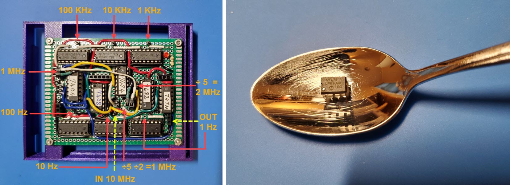
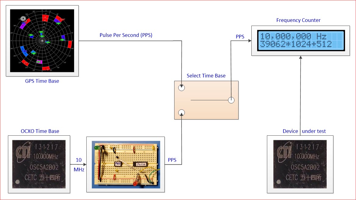
My OCXO page (linked above) describes using eleven
TTL chips to divide 10 MHz to 1 Hz, as a high-quality substitute for a
GPS pulse-per-second (PPS) time base in a frequency
counting application (left
image above). By comparison the leapsecond.com page claimed that the
chip in the teaspoon can be programmed to do the same thing. Indeed a
ready-made program for dividing 10 MHz to 1 Hz was supplied for
download (along with many others).
I confess to having been skeptical on first reading
about this MPU-based divider. However, I had previous experience with
programming a different PIC chip, and had documented that effort: https://www.lloydm.net/Demos/pickit3.html.
Emboldened by this prior experience I ordered two 12F675 chips from Amazon.
While waiting for them to be delivered I studied the PIC datasheet, not
all 136 pages of it, but key sections. Then I made a plan for
programming the chip, combining ideas from the previous project with
details from the datasheet. This preparation extended to wiring a
breadboard with connections in place, ready to plug in a chip as soon
as received from Amazon.
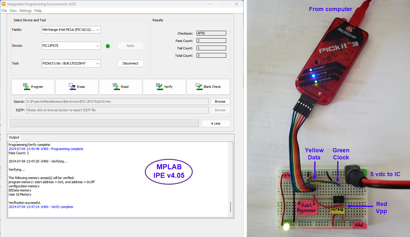
The chips were delivered earlier than expected and I
immediately set about to program them. According to the MPLAB
programming software output (above illustration), this attempt was
successful. Both chips were programmed to divide 10 MHz by 10 million,
one of them outputting a 1 Hz square wave and the other a 1 Hz 10
millisecond pulse. The true test would be whether either or both would
perform the programmed division.
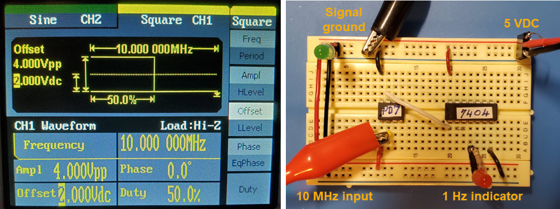
I elected to use a bench function generator in place
of an OCXO for initial testing. The bench instrument allows control of
waveform parameters, frequency, amplitude, shape, DC-offset, and more.
Side-by-side photos summarize the input signal definition (left)
and physical test setup (right). The +4 volts signal from the function
generator (red clip) connects to the input pin (#2) of the 12F675. The
output pin (#7) connects to a TTL inverter input. Two inverters in
series act as a buffer supplying the (hoped for) 1 Hz square wave
output to an LED indicator. As predicted, the LED blinked on and off
once per second. According to the divide program’s author, output
jitter had been measured to be less than 2 picoseconds.
Counting LED blinks over the span of one minute
proved that the divider was dividing, and that the result was roughly
as expected. It is unlikely that the function generator outputs exactly
10 MHz when set to that value. In fact I know from measurement that it
does not. Dividing any number in the neighborhood of 107
by
any other value from the same neighborhood would have passed the 60
beats per wristwatch-minute test. A more rigorous test setup was needed
to verify
that the 12F675 was dividing by exactly ten million.
Two oven-controlled crystal oscillators were
powered-on for approximately two hours, much longer than necessary to
stabilize for the test. One was verified or tweaked to oscillate at 10
MHz to within 1/4 Hz using the GPS-disciplined Frequency Counter. That
one served as the OCXO time base. The other was designated as the
device under test (DUT).
In the diagram above the double-throw switch labeled
‘Select Time Base’ was not an actual switch, but stands for unplugging
one time base and plugging in the other, an operation that took about
the same amount of time as throwing a switch would. One other
difference might be noted. For the LED blink test, the code that
produces a 1 Hz square wave ‘PD07’ was used. For this subsequent
comparison the code that produces a 1 Hz 20 msec pulse ‘PD10’ was used.
However, either divider would have produced the same result. I had just
wanted to exercise the pulse output. All in all, the bench setup was
somewhat messy. A couple of one-off adapter cables were involved and a
total of five devices each required 5 VDC power.
There was no reason for the DUT to generate 10 MHz.
Any stable high frequency would do for verifying (or not) the 12F675
divider’s accuracy. However, since two 10 MHz OCXO’s were available,
the 10 MHz
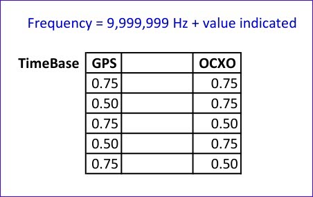
frequency was a convenient choice for the DUT. Over five
measurement trials with both GPS and OCXO, values ranged 1/4 to 1/2 Hz
low (e.g., 9,999,999.5 or .75 Hz). After performing these
five comparison measurements the time base OCXO was re-measured
at exactly
10 MHz. GPS. OCXO based tests were thus in agreement to within the
precision of measurement. This study proved to my satisfaction that the
12F675 divider is exact, as programmed.
Since the tiny 12F675 has been proven functionally
equivalent to the eleven-chip divider in the frequency counter
application, it would be possible to add an SMT version of the 12F675
to the frequency counter’s main board, and fully integrate switching
between time base sources. However, I did not plan to replace the
eleven chip divider in the frequency counter with either a main board
revision, or a single DIP-chip divider.
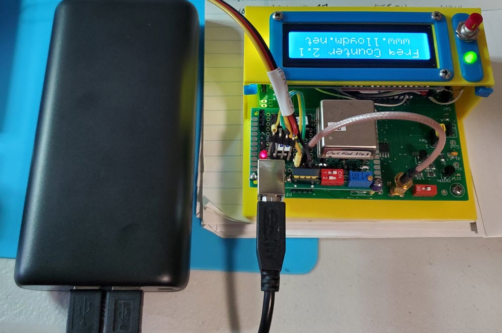
 That said, I had an earlier version of the frequency counter, one in
which the main board had some missing traces that were corrected by
wires. It would be easy to make a sub-board for that unit, in effect to
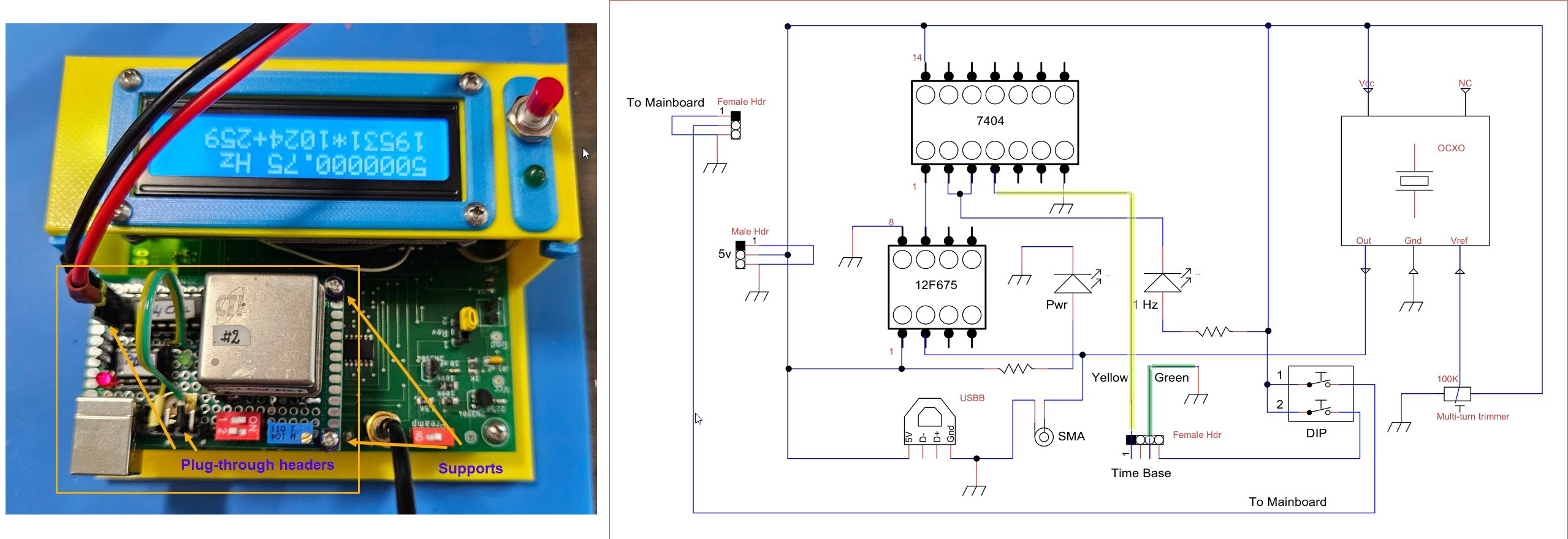
accommodate a built-in OCXO. The topmost illustration on this page
(left part) shows that sub-board mounted to the older frequency
counter’s main board via plug-through pin headers and a couple of
corner supports.
That said, I had an earlier version of the frequency counter, one in
which the main board had some missing traces that were corrected by
wires. It would be easy to make a sub-board for that unit, in effect to
accommodate a built-in OCXO. The topmost illustration on this page
(left part) shows that sub-board mounted to the older frequency
counter’s main board via plug-through pin headers and a couple of
corner supports.
After constructing a sub-board for the ‘yellow’
frequency counter I had the whimsical idea of calibrating its OCXO
using the same counter. This is not the same as spuriously calibrating
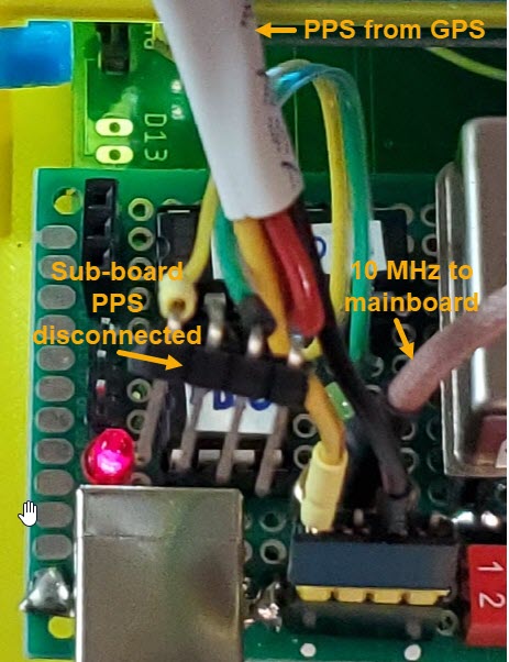
the OCXO using itself as time base. In the above photo the GPS is
connected to the time base pin header (yellow-black, left of the dual
DIP
switch), while the OCXO’s 10 MHz output connects directly to the main
board via a short SMA jumper. The annotated detail at the left may make
this arrangement clearer.
The OCXO had been calibrated the day before this
exercise, and was within ¼ Hz of 10 MHz after stabilizing. However, I
tweaked the multi-turn potentiometer about 1/16 turn to obtain a
consistent reading of 10 MHz exactly. Of course, the unadjusted reading
was good enough, and likely the best that should normally be expected
for off-line usage.
A brief note on the sub-board DIP switches: DIP
switch #1 controls power-sharing between sub-board and main board. If
this switch is OFF the main board can be powered via a through-header,
without powering the sub-board. Similarly the sub-board can be powered
independently, either via another header or via the USB-B jack. Switch
#2 determines whether the GPS should be powered from the unit. I use a
couple of different GPS’s, one of which is independently powered and
the other powered from the frequency counter. As a precaution, each GPS
has its own
interface cable. The one that is separately
powered does not have a power wire in its PPS interface cable.
In summary, the PIC12F675 divider concept is
entirely suitable for simplifying the Frequency Counter OCXO time base
circuit. Although its principal of operation differs in detail from the
TTL hard-wired divider chain concept, the result is the same.
Endnotes
1. Terrence Fugate (WN4ISX).
Project descriptions
on this page are intended for entertainment only.
The author makes no claim as to the accuracy or completeness of the
information presented. In no event will the author be liable for any
damages, lost effort, inability to carry out a similar project, or
to reproduce a claimed result, or anything else relating to a decision
to use the information on this page.