Not ham
radio: Unlike
most of my projects, this one had nothing to do with ham radio, and
very little to do with amateur electronics. I
was curious about whether
it would be
possible to construct an automaton to play the game
Connect
Four. The goal was simply to have fun.
 Connect
Four is not chess or Go, but is more complex than say
Tic-Tac-Toe or NIM. Although it is a solved game, Connect Four remains
interesting to play and interesting also as a programming
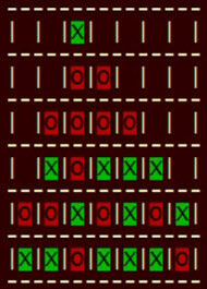
exercise. Some time ago I programmed a character cell version of the
game with a view to gaining experience with the minimax algorithm,
alpha-beta
pruning, and so forth. This exercise led me to wonder whether it would
be feasible to make a game playing
robot, replacing X's and O's with real physical pieces. Obviously at
some level the answer is yes—robots perform amazing tasks in
engineering and manufacturing contexts, but could I make such a thing
myself at
home, using only commonly available components?
Connect
Four is not chess or Go, but is more complex than say
Tic-Tac-Toe or NIM. Although it is a solved game, Connect Four remains
interesting to play and interesting also as a programming
exercise. Some time ago I programmed a character cell version of the
game with a view to gaining experience with the minimax algorithm,
alpha-beta
pruning, and so forth. This exercise led me to wonder whether it would
be feasible to make a game playing
robot, replacing X's and O's with real physical pieces. Obviously at
some level the answer is yes—robots perform amazing tasks in
engineering and manufacturing contexts, but could I make such a thing
myself at
home, using only commonly available components?
Preliminary
thoughts: To facilitate interfacing, the
game playing software should
be rewritten for a
microcontroller. It also seemed that to accommodate both game play and
interfacing, the project might require substantial CPU
power and memory. Based on such considerations I selected
a Teensy
microcontroller1,
along with a 2.8 inch touch
screen for the user interface. Meanwhile, I began
to look for some sort of inexpensive
robotic accessory
that could be pressed into service for the physical interface,
something
that had a chance
of working, but was not cost prohibitive—The project felt undeserving
of serious investment.
 Robotic Arm:
This SunFounder kit, touted as
a S.T.E.M.2
accessory, caught my eye because it was relatively inexpensive ($50 at
the time of purchase) and included an Arduino Uno, which would surely
facilitate the task of interfacing with a game-play microcontroller.
Moreover, the arm’s size and reach appeared large enough for
the project as envisioned.
Robotic Arm:
This SunFounder kit, touted as
a S.T.E.M.2
accessory, caught my eye because it was relatively inexpensive ($50 at
the time of purchase) and included an Arduino Uno, which would surely
facilitate the task of interfacing with a game-play microcontroller.
Moreover, the arm’s size and reach appeared large enough for
the project as envisioned.
In
photos the robotic arm looks metallic but it is actually made of shiny
black
plastic. Nevertheless, it is a fair value. There are four
servo motors. This number is sometimes referred to as the ‘axes’
or ‘degrees
of freedom’.
Basically, the robotic arm has four moving parts,
corresponding to rotation, lower arm angle, upper arm angle, and the
gripper’s
open-close angle.
Arduino software for operating the
servos by turning potentiometers (colored knobs in the photo) is available for
download from SunFounder. Installing this software is a numbered step in the kit
assembly instructions. The Arduino code itself serves to
document details of the robotic arm’s control and timing.

Technical
aspects:
This summary is not intended as a recipe for duplicating the
project. Rather it should be considered a guide, having
potential relevance to other similar projects. Teensy 3.5 and Uno
sketches
(links in software
paragraphs below) should also be regarded as descriptive
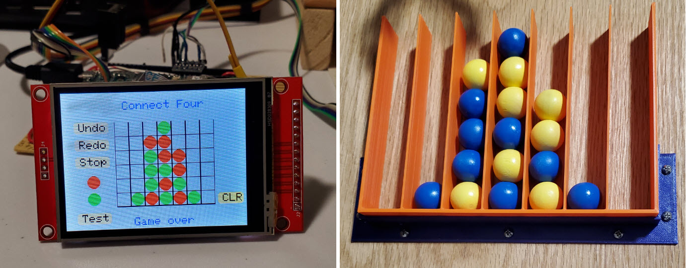
documents—ideas, rather than specifications. In lieu of a schematic,
the Teensy image reproduced above annotates interface connections.
External input
switches (if used) have pullup resistors on their normally
open contacts. Similarly, all interface pins on the touch screen are
pulled up to 3.3 volts through resistors. Normally closed switch
contacts are grounded and, as
indicated in the image, if switches are not connected then Teensy
pins 2 through 8 should be grounded. Alternatively, the sketch may be
edited to skip reading these pins.
The Uno does not need a separate diagram because its
external interface connections are annotated on the same image at
Teensy pins 24 through
27. All
connections are also documented in the sketches. One other detail—Uno
wants 5 volts to
assert logic high. Therefore Teensy-to-Uno interface pins are
routed via 3.3v-to-5v level converters. Level converter outputs connect
to Uno
digital input pins. Ground connects to ground, of course!
Software/Firmware:
The Teensy Arduino
sketch may be examined or downloaded here.
As it turned out only modest resources were needed (compiler statistics above). Game playing parts of the
code incorporate ideas gleaned from other
sources (attributions at bottom of sketch). The code also implements a
crude
search deepening function, so that play selection does not take
inordinately long, while the automaton still makes acceptable
moves.
Plays are communicated from Teensy to Uno as
column numbers.
Three I/O pins encode each selected column as a binary value 1 to 7.
(Zero is not used.) The fourth interface pin indicates ‘data ready’,
informing Uno to read the column to be played. Finally, the game part is self-contained so, for
what it’s worth, it
is also possible to play Connect Four on the touch screen independently
of
the robotic arm.
Uno:
The Connect Four robotic arm control sketch may be examined or
downloaded here. This
sketch should also be regarded as a collection of ideas. Different
physical
game play setups are bound to vary significantly, which would require
different arrays of target location constants at least, and likely
different movement combinations than this implementation-specific sketch illustrates.
Since the robotic arm potentiometers
(Uno analog inputs) are not involved in game play, there is no need for
raw 10-bit numbers in the servo control part. Thus, the various target
arrays
and constants define angles in degrees. Some program functions
are overloaded to interleave adjustments of more than one
servo and include parameterized timing, and so forth. These features
make for easy
experimentation in a way that should generalize readily to
similar projects.
At the time of purchasing the kit, I did
not realize that, in addition to the servo motor control pins, several
other digital I/O pins are exposed at the top of the robotic arm base.
Therefore, no soldering is needed for the Uno part of the interface.
Accessories:
The physical game array and related components are more completely
illustrated in the
demo video (link below). I placed a cut piece of poster board on
the table, in order to mark tentative component positions—in pencil, of
course,
anticipating erasures and re-markings. A 3D-printed ‘pickup tray’
(location of piece to be picked up and played) was affixed to the
poster board with double-sided adhesive tape. This was the main
reference
point for the setup. Next, the robotic arm was placed where it would
pick up the playing piece reliably and then its base was traced in
pencil. The
game array (also 3D-printed) was last to be positioned. A bracket
(blue colored part in photo at top of page) fixes
the position of the plastic
game array with respect to the wooden base. Finally, after adjustment
and testing, the location of the sloping plywood base was similarly
marked
on the poster board.

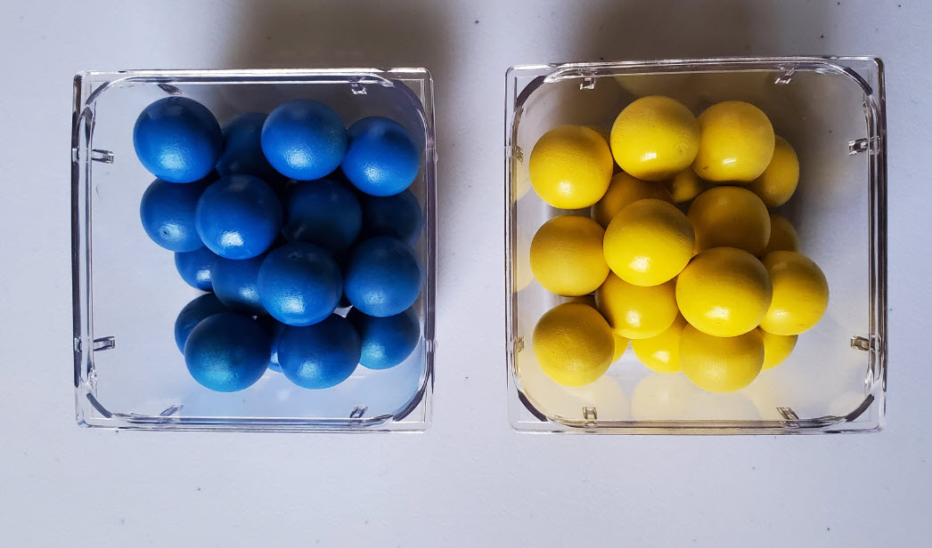 Playing
pieces are 3/4 inch wooden balls, spray painted in contrasting colors.3 Everything about the
playing pieces was wrong. The balls are roundish, but not round. Every
one of them has a small flat part somewhere. You don’t want the ball to
land
gently on its flat part. Of course, since they are not quite round,
their
diameters are also inexact, and generally slightly less than 3/4 inch.
Column spacing is approximately 7/8 inch so that the balls stack in
reasonably straight columns while not getting stuck between
dividing walls. As with the robotic arm purchase, the aim was to minimize
cost. Cork balls cost more than twice as much as wooden balls. I
would guess the same-size cork ones are rounder, although I have no
direct evidence of this.
Playing
pieces are 3/4 inch wooden balls, spray painted in contrasting colors.3 Everything about the
playing pieces was wrong. The balls are roundish, but not round. Every
one of them has a small flat part somewhere. You don’t want the ball to
land
gently on its flat part. Of course, since they are not quite round,
their
diameters are also inexact, and generally slightly less than 3/4 inch.
Column spacing is approximately 7/8 inch so that the balls stack in
reasonably straight columns while not getting stuck between
dividing walls. As with the robotic arm purchase, the aim was to minimize
cost. Cork balls cost more than twice as much as wooden balls. I
would guess the same-size cork ones are rounder, although I have no
direct evidence of this.
Painting the balls was also a bad idea.
The spray paint was sticky and remained so long after
application. It was suggested to me that dye would have been a better
choice.
For that matter it should only
be necessary to color half the pieces (the dark half) leaving the rest
unpainted.
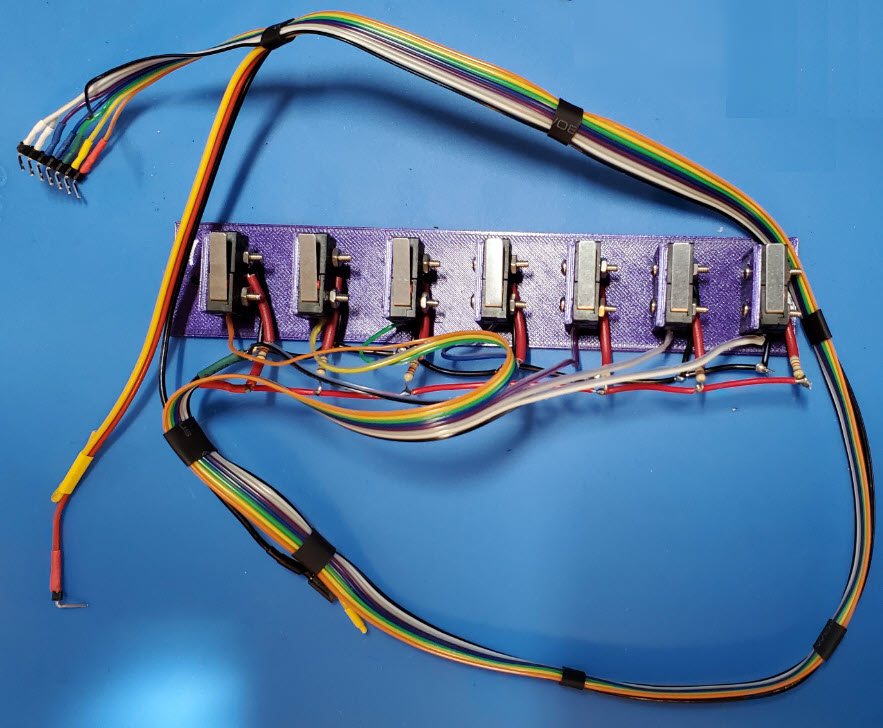
Inputs:
My ability to visualize physical concepts before they are put to the
test is not good, and so it was with the external input switch array.
At first I
thought of rolling the balls over embedded sensors. This seemed
ambitious, so instead I mounted an array
of
micro switches beneath the playing surface, where the (human) player
could
indicate the column played by clicking a corresponding switch. That
worked, but was too unwieldy to deploy as a
practical user interface. Fingers do not fit easily between the
robotic arm and the game so I removed and disconnected the switches,
substituting a dummy pin
header to
ground the associated Teensy input pins (as described above). At
present, the human player’s
moves are entered via the touch screen, a sort of cheat. To automate
game play more fully, a different sort of
layout would be needed—a better designed game array that could more
naturally incorporate non-mechanical sensors for detecting plays.
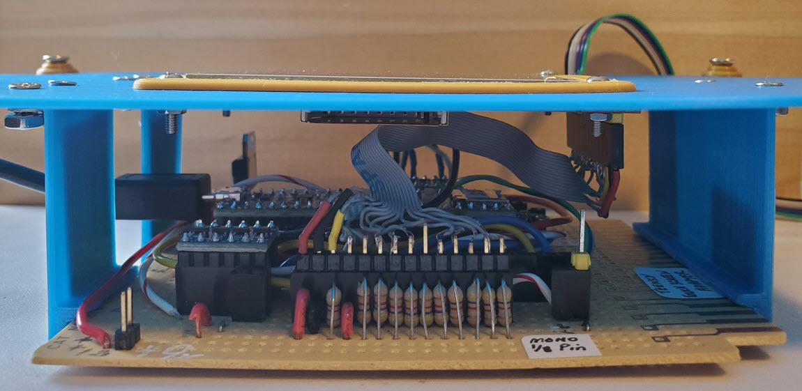
Wrap up: Thinking
ahead to the possibility or likelihood of reusing the enclosure
(plastic project boxes are also expensive), a 3D-printed panel
that replaces the box top includes slots (cutouts) for
passing USB and interface
cables to the outside. The circuit board attaches to the panel via slot
brackets, as shown in
the photo above, so there are NO HOLES in the manufactured plastic
project
box.
This
project was in part a simple exercise in interfacing, but it was more than that. A few years ago I had experimented with using a
single servo motor to rotate a remotely located air variable capacitor.
In the present project I learned, among other things, how to program
multiple servos to produce compound movements in more than one
dimension. Perhaps I am
easily satisfied. Learning
how to program the servos and
to have them execute game plays, however crudely, was rewarding enough.
It
is time to move on, or move back, as the case may be.
Demo video: SunFounder robotic arm plays Connect Four
1. I attempted to use a
Teensy 4.1, but could not get the touch screen to work
properly. This problem can no doubt be solved, but I lost patience with
it and switched to a Teensy 3.5, which I knew would work, based on
having
used one before in this project.
2. Science, Technology, Engineering,
and Mathematics, in the context of education.
3. Yes, I have noticed they are the
Ukrainian flag colors.
Project descriptions on this page are intended for
entertainment only.
The author makes no claim as to the accuracy or completeness of the
information presented. In no event will the author be liable for any
damages, lost effort, inability to carry out a similar project, or to
reproduce a claimed result, or anything else relating to a decision to
use the information on this page.